2
Specifications and Installation Instructions
Model 3100
Model 3200
Model 3300
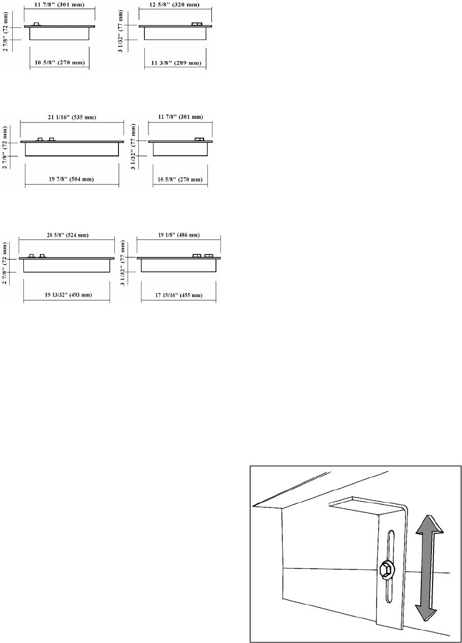
Dimensions and Specifications
Overall 11 7/8"L x 12 5/8"W x 3 1/32"D
mm 301 L x 320 W x 77 D
Cutout 10 7/8"L x11 9/16"W x 3 5/32"D
mm 275 L x 294 W x 80 D
Power requirements
120 V 60 Hz 1000 W 8.3 A 10 A breaker
230 V 50 Hz 1200 W 5.2 A 10 A breaker
Dimensions and Specifications
Overall 21 1/16"L x 11 7/8"W x 3 1/32"D
mm 535 L x 301 W x 77 D
Cutout 20 1/32"L x 10 7/8"W x 3 5/32"D
mm 509 L x 275 W x 80 D
Power requirements
120 V 60 Hz 2000 W 16.7 A 20 A breaker
230 V 50 Hz 2400 W 10.4 A 15 A breaker
Dimensions and Specifications
Overall 20 5/8"L x 19 1/8"W x 3 1/32"D
mm 524 L x 486 W x 77 D
Cutout 19 5/8"L x 18 1/8"W x 3 5/32"D
mm 498 L x 460 W x 80 D
Power requirements
120 V 60 Hz 3000 W 25.0 A 30 A breaker
230 V 50 Hz 3600 W 15.7 A 20 A breaker
Installation Guidelines
The stove should be installed in a location appropriate for
easy use and safe operation. A minimum clearance of 3-4
inches should be maintained in all directions.
Normal installation of the appliance requires a cutout in
the countertop of a dimension indicated in the
specifications. Insure there is no interference below the
countertop prior to cutting.
Allow for proper ventilation beneath the countertop. A
minimum of 3-sq. in. per burner is recommended.
(Example: Model 2300-3 burner X 3 = 9 sq. in total.)
Failure to provide adequate ventilation may result in poor
performance and is a potential fire hazard. In addition,
inadequate ventilation of the Origo cooktop may affect
proper operation of an adjacent built-in appliance.
The ceramic cooktop may be secured to the countertop by
two methods:
1. The metal frame should be bedded to the countertop
using a non-hardening compound that will permit later
removal without damage if service should be necessary.
2. Secure the cooktop to the countertop utilizing the two
brackets provided, adjust them to the countertop and
tighten screws. (See picture)
A three conductor, tinned stranded marine-type cable is
supplied with the appliance for connection to AC
electrical current only. Check the label on the product to
insure that the voltage of the unit matches the voltage of
the source. The color-coded wires are: Black L1 =
ungrounded conductor; White L2 = neutral; Green =
ground.
The electrical circuit should be fused with double pole
circuit breaker sized in accordance with the voltage and
amperage listed for that model in the specifications
section.


