


Version 07/08 - Page 5
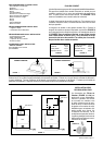
9.0 feet
10.0 feet
0.0 feet
19.0 feet
TOOLS NEEDED FOR INSTALLATION
• Saber Saw or Jig Saw
• Drill
• 1 1/4" Wood Drill Bit
• Pliers
• Phillips Screwdriver
• Wire Stripper or Utility Knife
• Metal Snips
• Measuring Tape or Ruler
• Level
• Pencil
• Caulking Gun
• Duct Tape
PARTS SUPPLIED FOR INSTALLATION
• 1 Backdraft Damper
• 1 Literature Package
PARTS NEEDED FOR INSTALLATION
• 2 Conduit Connectors
• Power Supply Cable
• 1 Wall or Roof Cap
• All Metal Ductwork
OPTIONAL ACCESSORIES AVAILABLE
• Charcoal Filters
For non-vented installations only,
replace charcoal lters as needed
part # 6093034
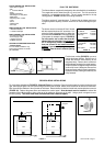
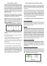
PLAN THE DUCTWORK
The Velvet slideout rangehood is designed to offer wide exibility of installations.
The rangehood can be ducted through a 6" round vent. The unit can also be
installed in a recirculating conguration. The unit comes standard in the top
venting position. FIGURE 3 shows recirculating installation.
The Velvet requires 6" round ductwork. To ensure that the blower performs to
its highest possible capacity, ductwork should be as short and straight as pos-
silbe.
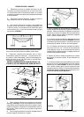
RECIRCULATING INSTALLATIONS
For recirculating installations (FIGURE 3), Charcoal Filters are necessary. Open the comfort panel by turning the knobs to the
right, slide open the glass visor, and remove the grease lters and set aside. Attach one charcoal lter to each end of the blower.
Each charcoal lter attaches to the of the side of the blower. Rotate the lter clockwise to install and counterclockwise to remove
(FIGURE 3A). Replace the grease lters and reattach the comfort panel. Some ductwork must be installed to exhaust the
rangehood back into the kitchen, either at the top of the cabinet or at the face of the soft. Using a plastic vent grate to cover
the duct opening.
This duct work must not terminate into a dead air space.
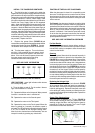
FIGURE 3A
45˚ Elbow
90˚ Elbow
90˚ Flat Elbow
Wall Cap
FIGURE A
9 Feet Straight Duct
2 - 90˚ Elbows
Wall Cap
Total System
FIGURE B
3.0 feet
5.0 feet
12.0 feet
0.0 feet
cabinet
ceiling
6” round
duct
hood
cabinet
ceiling
6” round
duct
hood
soft
vent grate
vent grate
FIGURE 3
The ductrun should not exceed 35 feet if ducted
with the required minimum of 6" round duct. Cal-
culate the length of the ductwork by adding the
equivalent feet in FIGURE A for each piece of duct
in the system An example is given in FIGURE B.
For best results, use no more than three 90°
elbows. Make sure that there is a minimum of
24" of straight duct between elbows if more
than one is used. Do not install two elbows
together. If you must elbow right away, do it
as far away from the hood's exhaust opening
as possible.
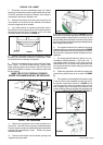
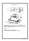
VERTICAL
DUCTING
FIGURE 2
HORIZONTAL
DUCTING
FIGURE 1
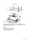
For direct rear venting (FIGURE 2), you must
change the blower position. Remove the 12
screws that hold the metal housing to the
rangehood body. Remove the 4 screws that
hold the blower housing to the metal housing.
Rotate the blower 90 degrees toward the back
and then ip it over 180 degrees. Be sure that
the power supply cable is properly positioned.
Replace all screws, making sure that they are
rmly fastened.