


Version 04/05 - Page 7
PREPARE THE WALL
1. Disconnect and move freestanding range from cabinet open-
ing to provide easier access to rear wall. Put a thick, protective
covering over cooktop, set-in range or countertop to protect from
damage or dirt.
2. Determine and clearly mark with a pencil the center line on the
wall where the rangehood will be installed.
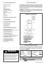
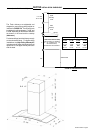
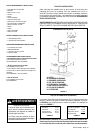
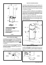
3. Based on your ceiling height and/or personal preference, deter-
mine the distance you would like between the bottom of the hood
and the cooktop (distance X in FIGURE 4A OR 4B). Draw a
horizontal line the height of distance X plus 12 3/8" (as indicated
in FIGURE 5).
FIGURE 5
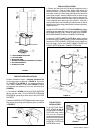
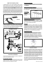
3. Hook the body on to the MOUNTING SCREWS (D in FIG-
URE 7) and fully tighten the MOUNTING SCREWS.
4. Adjust the leveling screws to level the CANOPY SEC-
TION.
5. For ducted installations, the DAMPER (H in FIGURE 1)
must be attached to the exhaust opening on the top of the
CANOPY SECTION. Connect the ductwork and seal all
connections with duct tape.
PROCEED TO "FOR ALL INSTALLATIONS" ON NEXT
PAGE
FIGURE 6
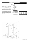
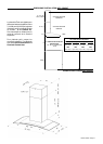
7. For the most secure installation, the MOUNTING SCREWS (D)
which mount the CANOPY SECTION (A in FIGURE 1) should be
installed into wood. Mark the wall along the horizontal line 4 9/16"
in from the center line on either side (as indicated in FIGURE 5A
or 5B) and install the MOUNTING SCREWS into the wall leaving
about 1/4" gap between the wall and the head of the screw.
8. For ducted installations, determine and make all necessary
cuts in the wall for the ductwork. Install the ductwork before the
rangehood.
9. Determine the proper location for the Power Supply Cable by
making sure it:
1) Allows the LOWER CHIMNEY COVER to hide the Field Wiring
Compartment.
2) Does not have ductwork blocking your access to the Field Wiring
Compartment.
Use a 1 1/4" Drill Bit to make this hole. Run the Power Supply
Cable. Use caulking to seal around the hole. DO NOT turn on
the power until installation is complete.
INSTALL THE RANGEHOOD
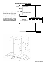
4. Place the UPPER CHIMNEY MOUNTING BRACKET (E) on
the wall as shown 1/16" from the ceiling, aligning the center notch
with the vertical center line. Mark the wall at the centers of the
holes in the bracket.
5. Place the LOWER CHIMNEY MOUNTING BRACKET (E) on
the wall as shown at 16 1/8" below the upper bracket, aligning
the center notch with the vertical center line. Mark the wall at the
centers of the holes in the bracket.
6. Install the CHIMNEY MOUNTING BRACKETS (E) on the wall
using the MOUNTING SCREWS (D) provided.
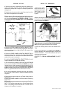
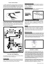
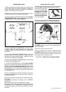
1. Remove the grease
filters from the unit by
pulling the knob forward
while turning it to the
left, releasing the lock-
ing lever.
2. Before mounting the CANOPY SECTION, tighten the two
leveling screws located near the CANOPY SECTION mounting
points as indicated in FIGURE 7.
FIGURE 7