


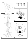

6
Insert the two extension tubes (Fig. 6.4 & Fig. 6.5) from
above the two structures by making them come down
to the appropriate hood seat. Lift the hood together with
the structure and the extension tubes to make the four
springs (Fig. 6.6-E) hook to the slots (Fig. 6.3-C). Then
tighten the two elements securely (Fig. 5.1 & Fig. 5.2)
with the safety screws (Fig. 5.2-A) and connect the hood
tube to the drain hole. Make the electrical connections.
(For versions with display only) Lift the lower pipe until
the cable strap coming out of the sucking unit is
uncovered and connect it to the display cable strap. Put
down the lower pipe while paying attention it is being
properly introduced into the hood.
Lift the upper tube (Fig. 6.5) up to the ceiling and insert
the two self-tapping screws (Fig. 6.5-D).
*Filtering model
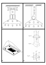
Place the upper plate (Fig. 4.1) on the ceiling. Drill 4 holes,
8 mm each, just next to the slots. Insert the plastic dowels
into the holes (Fig. 4.1-A). Fix the baffle (Fig. 4.2) to the
upper bracket (Fig. 4.3) with the four self-tapping screws
provided (Fig. 4.3A). Screw the plate together with the
baffle (Fig. 4.1B). Then fasten the lower structure (Fig. 6.2)
on the hood by making its holes and the metric-thread
screws welded on the fan support coincide (Fig. 6.1). Insert
the washers and nuts provided (Fig. 6.2-A) and screw with
an appropriate tool. Connect the drainpipe to the power
unit nozzle and fix securely with a hose clamp. Insert the
upper structure (Fig. 6.3) into the lowest one and adjust
its height as required by matching it with the cooktop’s
minimum height. Tighten the two structures securely with
the screws provided (Fig. 6.3-B). Insert the two extension
tubes (Fig. 6.4 & Fig. 6.5) from above the two structures
by making them come down to the appropriate hood seat.
Lift the hood together with the structure and the extension
tubes to make the four springs (Fig. 6.6-E) hook to the
slots (Fig. 6.3-C). Then tighten the two elements securely
(Fig. 5.1 & Fig. 5.2) with the safety screws (Fig. 5.2-A) and
connect the hood tube to the baffle’s lower hole.
Make the electrical connections. (For versions with display
only) Lift the lower pipe until the cable strap coming out
of the sucking unit is uncovered and connect it to the
display cable strap. Put down the lower pipe while paying
attention it is being properly introduced into the hood. Lift
the upper tube (Fig. 6.5) up to the ceiling and insert the
two self-tapping screws (Fig. 6.5-D).
Warning!
Before connecting the flexible exhausting pipe to the motor,
make sure the stop valve, which is on the air outlet of the
motor, can swing.
WORKING
Mod. 5CFB-36 IX luxury version (Fig. 7)
A: Light switch on/off
B: Motor switch on/off (1st rate level)
C: 2nd rate level switch
D: 3rd rate level switch
E: 4th rate level switch
MAINTENANCE
* An accurate maintenance guarantees good functioning
and long-lasting performance.
* Particular care is due to the grease filter panel. It can
be removed by pushing its special handle toward the
back-side of the range hood and turning the filter
downwards so as to unfasten it from its slot (Fig. 8).
To insert the filter just perform the opposite operation.
After 30 hours of operation, the push button control
panel will signal the saturation of the grease filter by
lighting all the buttons. Press the timer button to reset
. The grease filter should be cleaned by hand or in
dishwasher at least every two months or depending on
its use
* In case the appliance is used in its filtering version,
the active coal filter (Fig. 8Z) needs to be periodically
replaced. The coal filter can be removed by removing
the grease filter first (Fig. 8B), and by pulling its special
plastic tongue until it is unfastened from its slot. Re-
insert the coal filter by reversing the steps. The coal
filter needs replacing at least every six months depending
on the use.
* To clean the appliance itself tepid water and neutral
detergent are recommended, while abrasive products
should be avoided. For Steel appliances specialized
detergents are recommended (please follow the
instructions indicated o the product itself to obtain the
desired results).
* To replace the halogen lamps, remove first the glass-
blocking ring (Fig. 9A), by levering with a screw-driver
and thus removing the opaque glass (Fig. 9B) - when
performing this operation hold the opaque glass carefully.
Remove the lamp (Fig. 9C) without touching it with
uncovered hands. Replace it with another lamp of the
same kind. After the replacement, re-insert the glass-
blocking ring and fasten it.