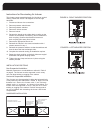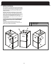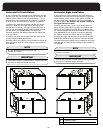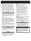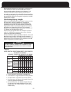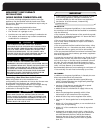
PROCEDURE:
This guide is intended specifically for PVC pipe; however,
the general procedure applies to all plastic piping systems.
MATERIALS: PVC Cleaner / Primer and PVC Solvent Cement.
After cutting pipe, remove all ragged edges and burrs.
This will reduce restriction (pressure drop) throughout
the venting and combustion air system.
IMPORTANT
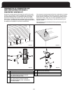
1. Cut the pipe end square. Chamfer edge of pipe. Clean
the fitting socket and pipe joint area of all dirt, grease
and moisture.
2. After checking the pipe and socket for proper fit, wipe
socket and pipe with cleaner / primer. Apply a liberal
coat of primer to inside surface of socket and outside
surface of pipe. DO NOT ALLOW THE PRIMER TO DRY
BEFORE APPLYING THE CEMENT.
If alignment is critical, make an alignment mark with a
lead pencil on the outside of the socket to the portion
of pipe beyond the joint. This will allow proper align-
ment as the joint is processed.
NOTE
Cement must be fluid; if not, re-coat.
NOTE
3.
Apply a thin coat of solvent cement to the inside sur-
face of the fitting socket. Quickly apply a heavy coat
of solvent cement to the pipe end and insert it into
the socket with a slight twisting motion until it bot-
toms out. If alignment is critical, match up the pencil
marks made prior to this step.
4. Hold the pipe in the fitting for 30 seconds to prevent
the tapered socket from pushing the pipe out of the
fitting. Failure to do this may result in a weak or leaky
joint.
5. Wipe all excess cement from the joint with a rag.
Allow 15 minutes before handling. Cure time varies
according to fit, temperature and humidity.
Observe shelf precautions printed on containers. Minimize
the exposure of the container’s contents to air.
For applications below 32°F (0°C), use only low
temperature-type solvent cement.
Stir the solvent cement frequently while using. Use a
natural bristle brush or the dauber supplied with the
container. If a dauber was not supplied, a 1 inch brush
is ideal.
NOTE
CAUTION
Moisture in the flue gases condenses as it leaves the
terminal. This moisture can freeze on exterior walls, on
soffits, and other nearby objects. Some discoloration is
to be expected; however, improper location or installa-
t
ion can cause structural or exterior finish damage to
t
he building. Caulk all cracks, seams or joints within a 6
foot radius of the termination.
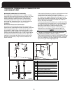
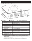
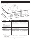
Direct Vent Piping Termination
General Guidelines
The external portion of the piping in all cases is to consist
of 2” pipe. If 3” pipe is used between the furnace and
terminal, transition to 2” within 18” or less of the exterior
wall.
When 3” pipe is used, exit the cabinet with 2” pipe.
Reduce or increase immediately after exiting the cabinet in
a vertical run making provisions to secure the vent bracket
between cabinet and fitting.
Avoid locating the terminals where the flue gas could
become stagnant and allow recirculation into the
combustion air intake.
Avoid locating the terminal in locations where dripping
condensate may cause problems such as sidewalks, patios,
above planters, near windows where exhaust gases may
cause fogging, etc.
A
void locating the termination too close to shrubs and
other vegetation. The condensate may stunt or kill them.
the termination.
Do not terminate under a deck unless there is adequate
clearance to prevent damage from the flue gases. A
termination may be located at the end of a patio deck.
Piping running beneath the deck must be suitably
insulated and suspended in a manner to prevent
condensate from collecting and freezing.
Do not locate the terminal on the side of the building
facing the prevailing winter winds.
Avoid locating the terminal in locations where dripping
condensate may cause problems such as side walks, patios,
above planters, near windows where exhaust gases may
cause fogging, etc. Avoid locating the termination too
close to shrubs and other vegetation. The condensate may
stunt or kill them.
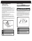
The vent terminal should be located no fewer than 6 feet
from an inside corner formed by two exterior walls. A 10
foot distance is recommended.
CAUTION
Improper location or installation can result in structural
damage to the building, damage to the exterior finish
of the building, or may allow recirculation or freezing
of the flue gases onto or into the combustion air
intake. Moisture in the flue gases condenses as it leaves
the terminals. This moisture can freeze on exterior
walls, soffits, and other nearby objects. Some discol-
oration is to be expected.
Caulk all cracks, seams or joints within a 6 foot radius of
17


