


Isotempâ Laboratory and Chromatography Refrigerators
Page 2 of 12
Part Number: 104416
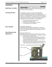
Installation
Selecting a Location
Leveling the Unit
Door Handles
Door Removal and
Adjustment
Choose a location for the refrigerator that will provide at least three
inches of clearance
between the cabinet and any adjacent vertical
surface at the sides and rear. Appropriate electrical power must be
available. Locate the refrigerator within 6 feet of the power outlet so
that no extension cord is required.
The refrigerator must be level in order to provide adequate
condensation drainage as well as proper door alignment and
operation. The refrigerator should be in its final operating location and
set so that it is firmly positioned on the floor. There are four leveling
screws, one on each corner. . Level the cabinet front to rear and side-
to-side using the corner leveling screws. The leveling screws are
accessed by removing the base grille, as described below:
1. Remove the lower grille attaching screws.
2. Grasp the grille with both hands.
3. Tilt the lower end of the base grille toward you.
4. Pull grille away from the refrigerator
(Swinging Door Models Only)
Door handles are packed inside each refrigerator. To mount the
handle, lift the door gasket behind the two screws on the front of the
door. Attach handle with offset away from the cabinet corner and
tighten the screws.
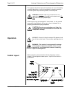
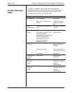
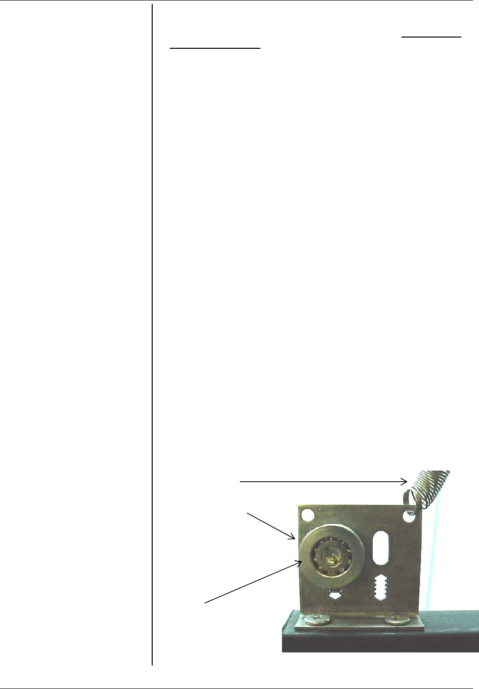
(Sliding Door Models Only)
Each door has its own closing spring located at the top of the door
track. Each spring is set for proper tension. If adjustment is required:
1. Check for cabinet level (see above).
2. Remove the door(s) by lifting it and sliding about half way
open. The roller will fall into a gap in the upper track. While
maintaining upward pressure on the door, pull the bottom
outward until it clears the bottom track.
3. Adjust the location of the door rollers in the roller brackets
(above door) as shown by loosening the lock nut on the back
of the roller bracket and moving the roller up or down.
Closing spring
Lock nut on back
Roller
Fig. 1