


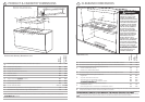
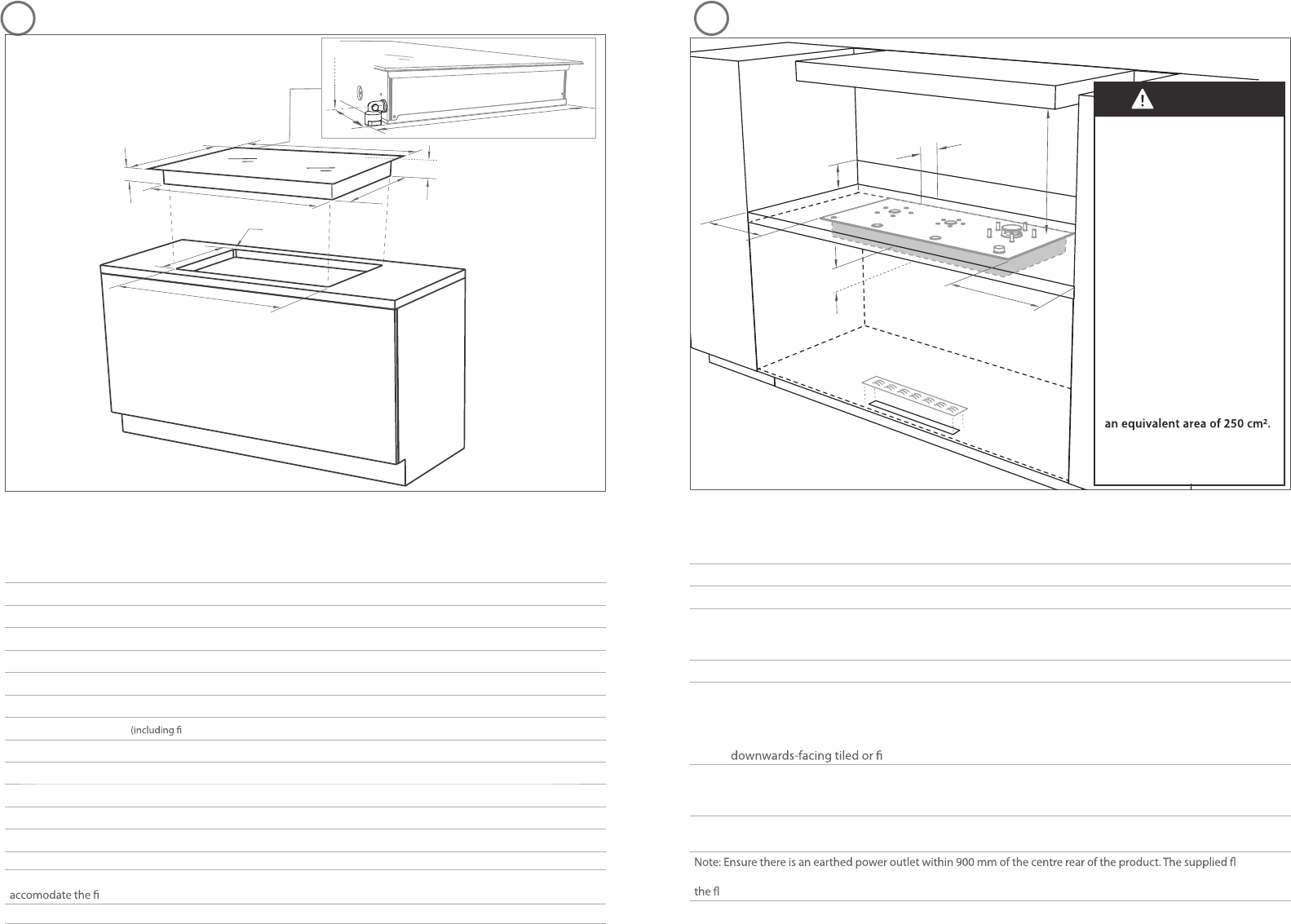
PRODUCT & CABINETRY DIMENSIONS CLEARANCE DIMENSIONS
Product and cabinetry dimensions (mm)
CG903ML
IZONA
CG903MLD
IZONA DEEP
A
overall height of product (including retracted dials/pan supports) 96 96
B
overall width of product 900 900
C
overall depth of product 410 530
D
height of chassis (below top of bench) 89 89
E
width of chassis 856 856
F
depth of chassis 384 480
G
depth of chassis tted elbow*) 424 480
H
overall width of cutout 865 865
I
overall depth of cutout 390 494
J
corner radius of cutout max. 10 max. 10
K
distance from top of bench to centre of gas inlet on product 64 64
L
distance from edge of chassis to gas inlet on product 20 20
Note: *(CG903ML models only) If benchtop thickness exceeds 50 mm, additional cutout space will be required to
tted elbow.
Installation diagrams for illustration purposes only
Note: Gas inlet connection is
located in the back left corner.
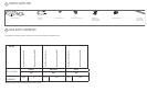
Clearances (mm)
CG903ML
IZONA
CG903MLD
IZONA
DEEP
A
minimum clearance from left edge of product to nearest combustible surface 60 60
B
minimum clearance from right edge of product to nearest combustible surface 80 80
C
minimum clearance from rear edge of product to:
nearest combustible surface
nearest non-combustible surface
100
10
10
10
D
minimum height of non-combustible material when used on adjacent walls 150 150
E
minimum clearance from glass surface to:
rangehood
any other overhead exhaust fan
downward facing combustible surface
re resistant surface
650
800
650
500
650
800
650
500
F
minimum clearance below top of benchtop to:
combustible surface
Fisher & Paykel oven or nearest non-combustible surface
115
100
115
100
G
cutout measuring 50 x 500 mm for air intake grill. Ensure air can easily enter the area around the base of
the product from the room in which the product is installed
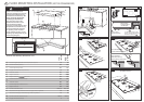
exible
hose must be used between the product gas inlet and the connector on the wall which should be 650 - 750 mm above
oor and towards the left-hand end of the product. It should be accessible with the product installed.
A
B
C
G
D
E
F
32
A
B
C
E
D
F
H
I
J
K
L
G*
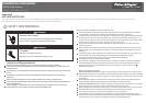
WARNING!
The CookSurface requires
adequate air supply to fully
function. The base of the
CookSurface must have direct
unrestricted ventilation to the
room where the CookSurface
is installed. Do not ventilate
the base area to an external
area that can be at dierent
air pressure to that of the
burners. You may ventilate
from adjacent cupboards, but
ensure that the available air
supply will not be restricted.
The ventilation area must
be 500 x 50 mm or of an
equivalent area. If the 50 mm
wide slot is not possible due
to the width of the available
toe recess, increase the length
of the slot so as to maintain
An air intake grill is provided.
Ensure that the grill is not
covered or obstructed.
Flush