


2
2
3
5
6
7
8
9
10
4
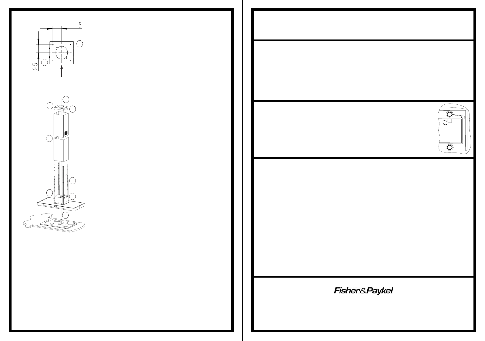
PLAN VIEW OF SUPPORT FRAME
FRONT FACE OF CANOPY
INSTALLATION - DUCTED
Before drilling any holes check that the area behind
the surface to be drilled is clear of any electrical
cables, pipes etc. Fixing to a solid joist or 50mm
deep truss is recommended.
Whenever possible protect the hob top with
cardboard or the like.
1. Before commencement unpack the canopy hood
and check that it functions correctly.
2. Use a plumb line to mark the centre of the
cooking surface on the ceiling.
3. Using the ceiling bracket as a template mark the
four holes on the ceiling. Ensure that the ceiling
bracket front edge is parallel with the bench top
and that the plumb line mark is central to the four
mounting screw holes.
4. Drill holes in the ceiling at the points marked.
a. When fitting to a 50mm truss drill a pilot
hole through the ceiling and into the truss.
b. If securing to any other ceiling type please
use appropriate fasteners and follow their
instructions of use carefully.
5. For the ducting mark out and cut a Ø170mm hole
in the ceiling.
6. Fix the ceiling bracket to the ceiling using the
screws supplied.
7. Using duct tape secure the ducting to the top of
the motor housing. Solid ducting, galvanized or
plastic is recommended. Use flexi ducting only
in difficult installations and if used ensure that it
is pulled tight. The smoother, straighter and
shorter the ducting the quieter and more efficient
the canopy hood will perform. Tape the power
plug to the top of the ducting, this will enable
easy access to the plug after installation.
8. Mount the first set of four angle brackets on the
canopy. Use eight self tapping screws, one per
side per corner.
9. Determine the installed height of the canopy and attach the second set of four angle brackets to the
first to achieve this height. Secure with eight self tapping screws, one per side per corner.
10. Strip the plastic protective film off the two chimney pieces and place these over the corners. The
lower chimney will rest on top of the canopy hood and the upper chimney will be extended and
secured to the ceiling bracket. To ensure that the upper chimney does not slip inside the lower
chimney, secure it so that the upper chimney is showing. Duct tape or placing two screws/nails
through the upper chimney securing holes will do this.
11. Offer the canopy hood, angle brackets, chimneys and ducting up to the ceiling bracket and secure in
place with eight screws provided, one per side per corner. The dimension between the filters and the
cooking surface should be in line with those suggested in the ‘height of canopy hood’ section. An
additional person will be required for this operation or a simple support frame manufactured to the
correct dimensions will aid assembly of the Designer Island canopy hood.
12. Finish assembling the ducting ensuring the path is as short, straight and smooth as possible.
13. Connect to the power supply and switch on the power using switch/socket outside the canopy hood.
14. Slide the upper chimney piece up to the ceiling and secure in place with four screws supplied.
INSTALLATION – RECIRCULATED
For recirculation do not cut the 170mm hole into the ceiling and purchase the charcoal filters and recirculation
kit 1744. The recirculation kit must be used to channel the air to the top of the flue. For other accessories parts
and service please contact your local supplier or approved service agent.
MAINTENANCE
The manufacturer is not liable for any damage caused by not following these instructions.
Particular care must be taken with the grease filters which must be periodically cleaned (at least
every two months). Remove the grease filters and wash them either by hand in hot soapy water or
in the dishwasher using mild detergent. Note: some discolouration of the frame may occur.
Caution: Never use abrasive or oil based liquid cleaners. To clean the stainless steel and glass
components of the canopy hood use mild detergent and warm water. In areas of high humidity and
coastal environments cleaning should be carried out frequently.
For accessories, parts and service, please contact your local supplier (refer to the warranty certificate).
LIGHT REPLACEMENT
(Halogen bulb 12 Volts/20 Watt)
1. Switch off the power to the canopy hood.
2. Use a small bladed screwdriver to prise off the light cover taking care not to
damage the surrounding material.
3. Remove the defective bulb from the canopy hood.
4. Replace with a new bulb using a cloth. Do not touch the bulb with fingers.
5. Snap the cover back into place.
WARNINGS
• This canopy hood is not intended for use by young children or infirm persons without
supervision.
• Young children should be supervised to ensure that they do not play with the canopy hood.
• There shall be adequate ventilation of the room when the canopy hood is used at the same time
as appliances burning gas or other fuels. (A partial vacuum in the room could result in too high
a concentration of gas in the air).
• You must read the details concerning the method and frequency of cleaning.
• There is a fire risk if cleaning is not carried out in accordance with the instructions.
• Do not flambé under the canopy hood.
• Exhaust air must not be discharged into an existing flue which is used for exhausting fumes
from appliances burning gas or other fuels.
• The minimum distance between the hob surface and the filters of the canopy hood shall be
600mm (650mm if installed over a gas hob).
• Attention should be given to ensure that any applicable regulations concerning the discharge of
exhaust air is fulfilled.
• If the supply cord of this equipment is damaged it must only be replaced by the manufacturer, its
service agent or similarly qualified person in order to avoid a hazard.
Electrical Rating:
310W (1.28 A)
Max at 240V 50Hz
Manufactured for
By:
Robinhood Ltd
6 Zelanian Drive, East Tamaki
Auckland, New Zealand
ISO9001 Certified
104923 issue A
ECN 06 037