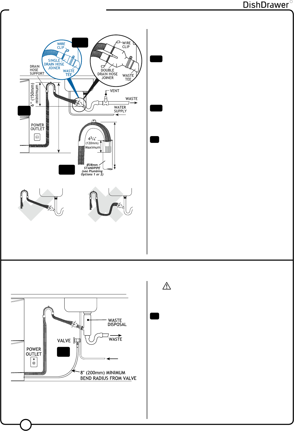
Attach the Drain Hose Support to the cabinetry (with the screw
supplied) to prevent siphoning and to keep the drain hose(s)
from kinking. If required, the Drain Hose(s) may be trimmed to a
suitable length.
29
1
/
2
” -
34
3
/
4
”
(750mm - 882.5mm)
29
1
/
2
” -
34
3
/
4
”
(750mm - 882.5mm)
DishDrawer® with Hose Joiner (see Plumbing Options).
Remember to slip the wire clip(s) on the drain hose(s) first.
Important!
Minimum hole size to be connected to the waste tee is
1
/
2
”
(12.7mm).
Be sure the Drain Hose(s) are fully extended to prevent sagging
(see diagram to the left).
The Drain Hose support must be used.
Drain Hose joiner must not support weight of hoses. Keep
excess length of Drain Hose on the DishDrawer® side of the
Drain Hose support or trim to suit.
When using the standpipe option (see Plumbing Options), hose(s)
should not extend further than 4
3
/
4
” (120mm) down the standpipe,
in order to prevent siphoning.
Slip a wire clip over each drain hose, then push the hoses into
the Drain Hose Joiner firmly, 5 clicks. Position the wire clip(s)
between the two positioning ribs on the Drain Hose Joiner.
Attach the Drain Hose Joiner to the waste tee (see Plumbing
Options). Ensure a snug fit. If required a hose clamp may be used.
R
INSTALLATION INSTRUCTIONS
STEP 7: CONNECTING THE DRAIN HOSE(S)
NOTE: SINGLE MODELS DO NOT HAVE A TOE KICK TO
INSTALL. PROCEED TO STEP 12 FINAL CHECK LIST.
WARNING!
DO NOT plug the product in
at this stage.
Important!
DO NOT cut the inlet hose.
19
Connect the Inlet Hose to the water supply. Be sure the sealing
washer is in place. The hose coupling must be tightened a further
half turn after seal contact.
TIP - Turn the water valve ON to check for any leaks.
Alternatively flexible stainless steel hose can be plumbed directly to
the inlet valve using a
3
/
8
” brass adaptor (p/n 526161) available from
the nearest Fisher & Paykel Authorized Service Agent.
18a
19
20
STEP 8: CONNECTING THE INLET HOSE
10
18a
18b
18b
WATER
SUPPLY
20


