


10
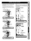
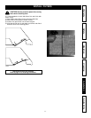
WARNING: Risk of electrical shock. Electrical
wiring must be done by qualified personnel
in accordance with all applicable codes and
standards. Before connecting wires, switch
power off at service panel and lock service
disconnecting means to prevent power from
being switched on accidentally.
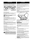
1. Remove wiring cover from rough-in plate and set aside.
2. Remove appropriate knock-out from rough-in plate. As you
are installing the rough-in plate, feed 6” of power cable
through knock-out opening and attach cable to wiring box
with appropriate connector.
3. Connect BLACK to BLACK, WHITE to WHITE and GREEN
or bare wire under GREEN ground screw. Reinstall wiring
cover.
CONNECT THE WIRING
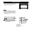
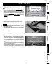
FINALIZE THE INSTALLATION
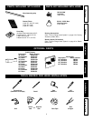
OPTION
A Soffit Chimney is available - to hide ductwork if the hood
is not installed under a cabinet. Refer to the instructions
included with the soffit chimney.
Refer to page 5 for ordering information.
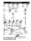
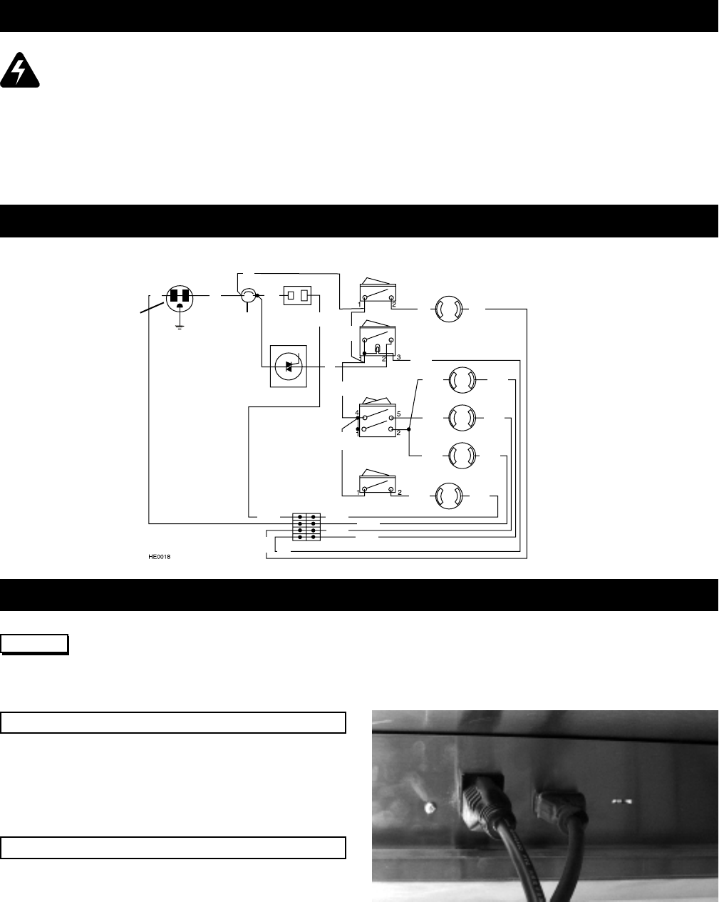
1. To install blower, refer to instructions included with blower
/ rough-in kit. Once the blower is installed, plug the blower
unit into the female receptacle and the power supply onto
the male connector inside the hood. DO NOT plug the two
cords into each other.
2. Install (2) heat lamp bulbs. Use BR40 size, 250W Max.,
infrared bulbs only (purchase separately).
Install (3) halogen light bulbs. Use PAR20 50W size
(purchase separately).
See page 6 for blower / rough-in kit information.
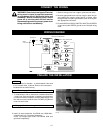
WIRING DIAGRAM
120V 60Hz IN
NEMA
5-15P PLUG
G
W B
HS
THERMOSTAT
B
B
TO FAN MOTOR
W
B
SPEED
CONTROL
B
B
B
LEFT HEAT
LAMP SWITCH
RIGHT HEAT LAMP SWITCH
RIGHT HEAT LAMP SOCKET
RIGHT LIGHT
SOCKET
FAN SWITCH
CENTER LIGHT SOCKET
LEFT LIGHT SOCKET
LEFT HEAT LAMP SOCKET
LIGHT
SWITCH
B
W
W
W
W
W
W
B
B
B
B
W
W
W
W
W
W
W
HE0003
TERMINAL BLOCK