


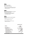

STEP 7
INSTALLING THE BACKGUARD – SEALED BURNER MODELS
NOTE: PLEASE READ ALL INSTRUCTIONS BEFORE STARTING INSTALLATION.
7-1
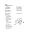
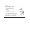
Remove the burner grates, griddle/grill and housing.
7-2
From the front of the range, remove the Phillip screws in the rear of each burner pan (black pan
where the top burners are located).
7-3
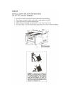
From the rear of the range, remove two screws from the rear of the side panels, the upper most
screw on each side. You will need a
5
/
16
” nut-driver or
5
/
16
” socket to remove these screws. (Tools
with a magnetized tip will be helpful in replacing the backguard screws.)
7-4
From the rear of the range, locate the upper wire cover with tab slots. Remove two
5
/
16
” mounting
screws. This cover will be reinstalled once the backguard is installed.
7-5
Screws are installed in the backguard, at the Factory for assembly to the backguard support. It is
important that you locate and remove these four screws from the backguard before you attempt to
install the backguard to the range backguard support.
7-6
Remove the vinyl protective covering from the front of the backguard.
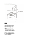
7-7
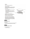
The front of the backguard should fit between the back burner pans and the rear support. If the
burner pan and rear support have a tight tolerance, place a thin bladed screw driver at either end,
between the burner pan and rear support, to start placement of the backguard. Slide the backguard
over the exhaust vent(s). Align the slots in the front of the backguard with the rear support bar
locator studs.
7-8
With the backguard in position, secure the backguard to the rear backguard support using the four
5
/
16
” screws removed in step 7-4, re-install the screws in the edge of the side panels and replace
the screws in the back of each burner pan. Re-install griddle/grill housing. Do not re-install the
grates at this point.
7-9
Reinstall the upper wire cover that was removed in Step 7-4. Place the cover into position with
the lower backguard panel fitting into the tab slots. Reinstall the two
5
/
16
” mounting cover screws.