


9
PrP: Printer presence. (Yes or no) Enables or disables the printer.
ItP: Printing interval. (0.0 to 30.0). Sets the print interval.
PbP: Print probe selection. (iP: only the food probe selected. rP: only the air probe selected. irP: Food and Air
probe selected. irE: All probes selected).
PtH: (yes or no) Enables or disables the printing during the holding phase.
tSt: Starts the controller self test function.
Out: Exit from the menu.
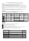
Parameter Access and modification
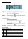
To access the parameters firstly enter the function menu by pressing the “SET” and “DOWN” keys for 3 seconds.
Scroll through the labels and select “PR2”, press the “SET” key. “PAS” label flashes for a few second followed by
“0 _ _” with the zero flashing. The access code is ‘ 321’.
Use the “UP” or “DOWN” key to input the first number of the security code in the flashing section, confirm by
pressing “SET”.
Repeat the operation for the second and third digits.
If the security code is correct “Hy” will be displayed.
NOTE: if no key is pressed for 15 seconds the controller reverts to displaying the room temperature.
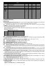
Parameter Settings
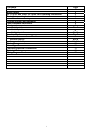
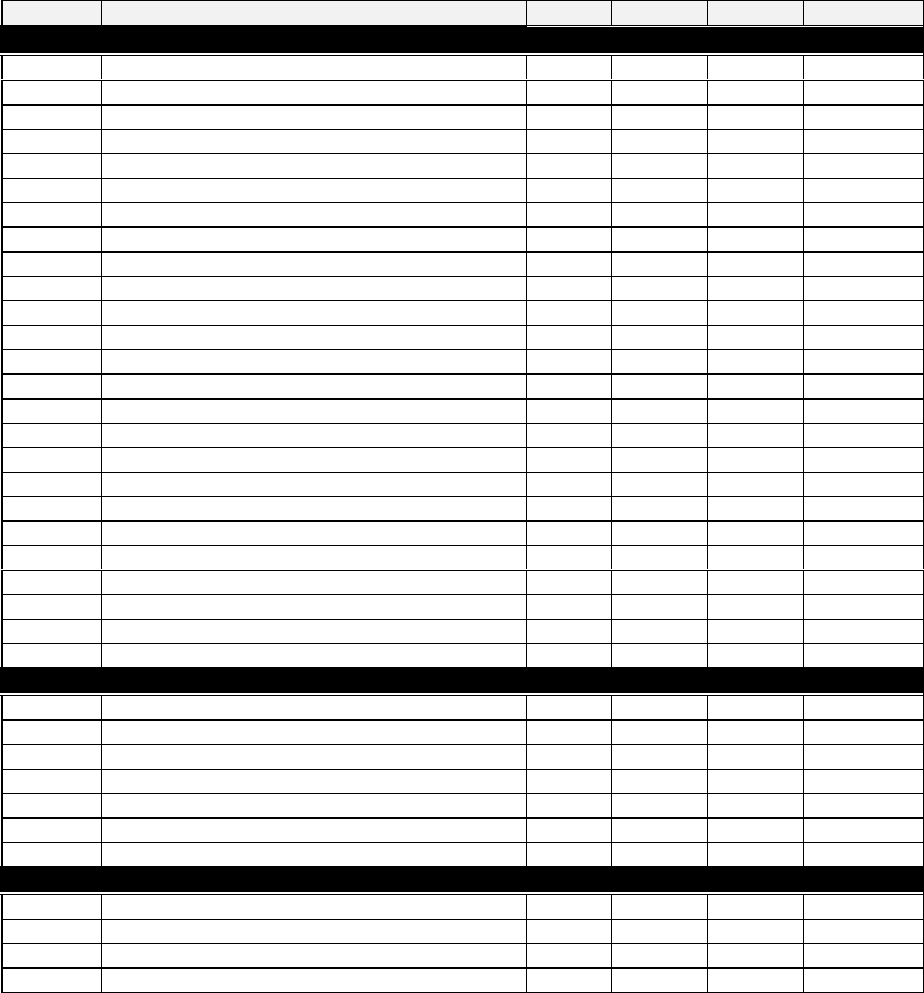
Lab Description Default QC 11 QC 600 BQCF 40
Regulation
Hy
differential
3 3 3 3
AC
Anti-short cycle delay
2 2 2 2
1c2
Second compressor configuration
0 0 0 0
rPO
Thermostat probe calibration
0 0 0 0
EPP
Evaporator probe presence
YES NO YES YES
EPO
Evaporator probe calibration
0 0 0 0
iPP
Insert probe presence
YES YES YES YES
iPO
Insert probe calibration
0 0 0 0
CF
Temperature measurement unit
°C °C °C °C
rES
Resolution (for °C):
IN IN IN IN
PAU
Time of stand by
1 1 1 1
PFt
Maximum acceptable duration of power failure
2 2 2 2
iPd
Temperature difference for the automatic recognition of the insert probe
3 3 3 3
iPt
Time delay for the automatic recognition of the insert probe
60 60 60 60
Con
Compressor ON time with faulty probe
15 15 15 15
COF
Compressor OFF time with faulty probe
10 10 10 10
diC
Digital input operating mode
dor dor dor Dor
diP
Digital input polarity
OP OP OP OP
did
Digital input delay
5 5 5 5
OAC
Auxiliary output configuration
AL AL AL AL
OAP
Auxiliary output polarity
OP CL CL CL
OAt
AUX output timer
60 60 60 60
OAS
Set point for AUX output
0 0 0 0
OAH
Differential for AUX output
2 2 2 2
OAi
Probe selection for the AUX output
rP rP rP rP
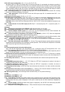
Defrost
tdF
Defrost type
in in in In
dPO
Defrost before holding cycle
YES YES YES YES
IdF
Interval between defrost cycles
6.0 6.0 6.0 6.0
dtE
Defrost termination temperature
20 20 20 20
MdF
Maximum length for defrost
20 20 20 20
dFd
Temperature displayed during defrost
rt rt rt Rt
Fdt
Drip time
1 1 1 1
Fans
FnC
Fan operating mode
c_n O_Y O_Y O_Y
FSt
Fan stop temperature
30 30 30 30
AFH
Differential for the stop temperature and for the alarm
2 2 2 2
Fnd
Fan delay after defrost
2 2 2 2