


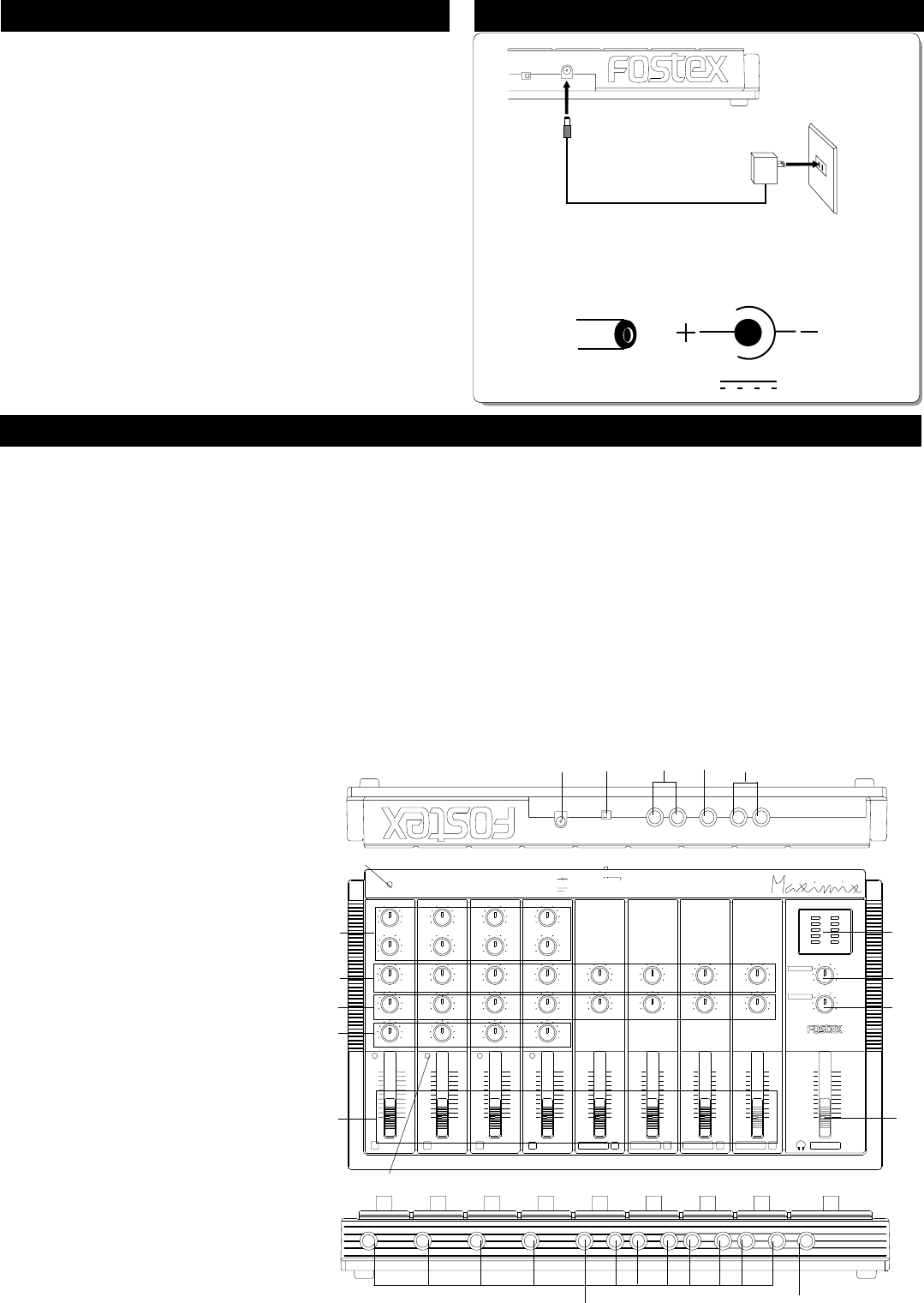
Connecting the AC adaptorImportant Notes in Operation
Plug the AC adaptor cable into
the MN12 DC IN jack and plug
the AC adaptor into the wall
outlet.
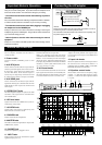
Names and Functions
1. DC IN jack
The AC adaptor included with the MN12 is
connected here.
14. Panpot knobs
Adjusts the sound position when signals input
to each input jack is output to the STEREO OUT
(L, R) jacks.
12. INPUT jacks
External sound sources are input here.
INPUT 1~4 complies to mic/line and levels
controlled with the TRIM knobs to match the input.
INPUT 5~12 are exclusively for line level inputs
and are in stereo. If monaural sound sources are
to be input, they should be connected to the MONO
marked 5, 7, 9 and 11 jacks, and for stereo, to the
5-6, 7-8, 9-10 and 11-12 jacks.
PHONES
10
5
0
AUX
RL
PAN/
BAL
10
5
0
AUX
RL
PAN/
BAL
10
5
0
AUX
RL
PAN/
BAL
0
+-
EQ HI
+
0
-
EQ LO
10
R
MIC
5
0
L
LINE
AUX
PAN
TRIM
0
+-
EQ HI
+
0
-
EQ LO
10
R
MIC
5
0
L
LINE
AUX
PAN
TRIM
0
+-
EQ HI
+
0
-
EQ LO
10
R
MIC
5
0
L
LINE
AUX
PAN
TRIM
0
+-
EQ HI
+
0
-
EQ LO
10
R
MIC
5
0
L
LINE
AUX
PAN
TRIM
POWER
PEAK
1234
PEAK PEAK PEAK
10
5
0
AUX
RL
PAN/
BAL
0
5
10
0
5
10
0000
5555
10101010
0
5
10
0
5
10
0
5
1010 10 10
555
000
10
5
0
5/MONO 6
MASTER
10
5
0
10
5
0
AUX RTN
7/MONO 8 9/MONO 10 11/MONO 12
MN12
LR
+
-
10
5
0
3
6
DC IN
12V
-
+
STAND BY ON
L/MONO
AUX RTN
R
AUX SEND
LR
STEREO OUT
* Avoid using headphones for long hours at high volume levels.
Doing so can result in hearing failure. Any sudden increase in headphone sound
levels must also be avoided. This could result in damage to your hearing.
* Turn down all sound volume controls when switching on power to
this mixer.
Also, turn all volume controls when switching on/off power to the MN12. Otherwise,
a sudden loud noise could have a bad affect on you ears and your hearing.
* Turn down the sound volume control when plugging or unplugging
the headphone into the PHONES jack.
Always turn down the sound volume control when connecting or removing the
headphone plug from the PHONES jack. Doing so with the volume control turned
up, could result in hurting your ears.
* Switch off power to the mixer when interconnecting it to external
equipment.
Always be sure to switch off the MN12 power when interconnecting external
equipment to the MN12.
11. INPUT fader
Adjusts input level of the sound source signal
applied to input jack 1-12.
10. PHONES jack
Monitor headphone is plugged in here.
2. Power switch
Switches ON-OFF (STANDBY) power to this
mixer.
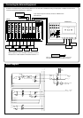
15. Input trim knobs
These are adjusted to match the output level of
the sound sources connected to INPUT 1~4
(adjusting range is -60dBV~-10dBV). If the PEAK
LED blinks, the levels with this knob.
16. Equalizer control knobs
These knobs control the low frequency range
(100Hz, +/-13dB) and high frequency range
(10kHz, +/-13dB) of the input signals of INPUT
1~4 jacks.
13. AUX send knobs
The AUX send knobs determine the level of the
input signal that will be sent to AUX SEND jacks.
The signal adjusted by these knobs can be sent
to an external device, such as an effect unit.
9. MASTER fader
This fader controls the signal that is output from
STEREO OUT L, R jacks.
8. PHONES knob
Adjusts sound of the headphones.
7. AUX RTN knob
Signals effect processed are adjusted by this
knob and sent to stereo L and R.
6. LED level meter
Signals levels from the STEREO OUT jacks are
indicated by these LED'S.
5. STEREO OUT jacks
The mixed signals is output to inputs of the MTR
and Mixer. The output level is controlled with
the MASTER fader.
4. AUX SEND jack
This is connected to the effector input and the
signals for effecting are controlled with the AUX
SEND knobs on their respective channels and
then output.
3. AUX RTN jacks
This is connected to the effector output and the
effector processed signals sent to the stereo L,
R connectors. Input signals are adjusted with
the AUX RTN knob. If the effector output is
stereo, they are respectively connected to L and
R, and if output in mono, it is input to L/MONO.
1 2
3
4
5
6
7
8
9
10
12
13
11
14
15
16
PEAK LED
POWER LED
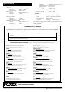
<NOTE>
Unplug the AC adaptor from the wall outlet if the MN12 is not to be
used for long hours or extensive periods of time.
The schematic is indicates that the outer sheath is minus polarity, and
the power supply is DC 12V.
DC IN
12V