


EN
8
8
INSTALLATION
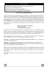
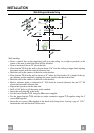
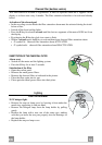
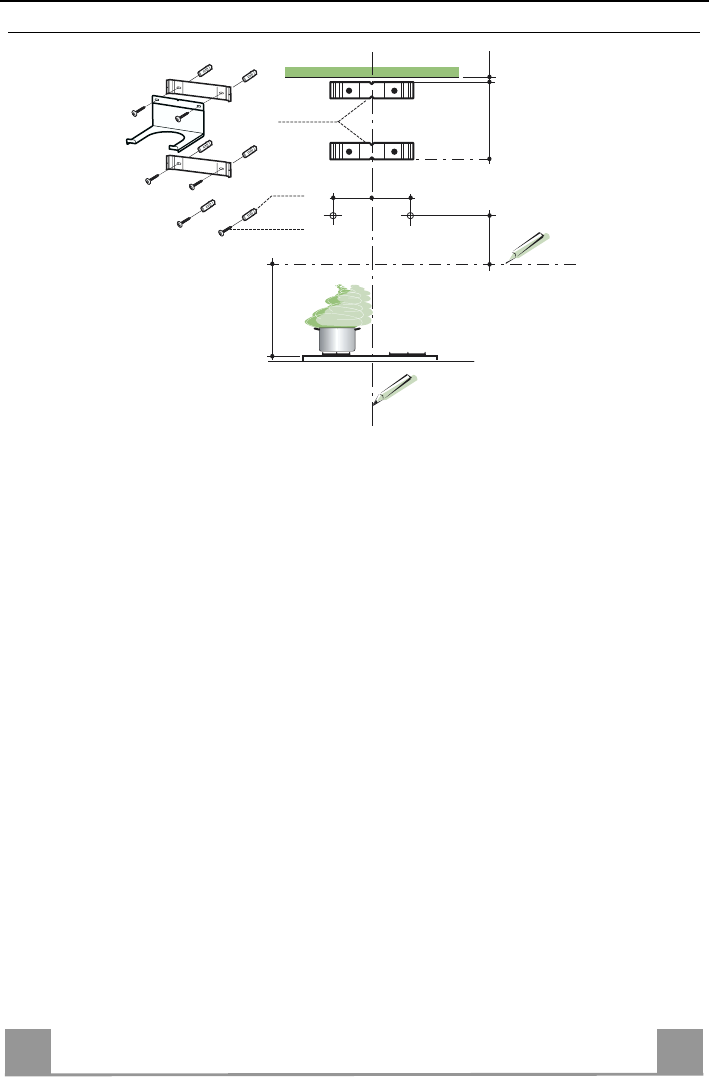
Wall drilling and bracket fixing
11
12a
13" 3/8
X
÷1/16"
4"9/16
24"
7.2.1
4"9/16
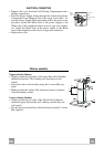
Wall marking:
• Draw a vertical line on the supporting wall up to the ceiling, or as high as practical, at the
center of the area in which the hood will be installed.
• Draw a horizontal line at 24” above the hob.
• Place bracket 7.2.1 on the wall as shown about 1/16” from the ceiling or upper limit aligning
the center (notch) with the vertical reference line.
• Mark the wall at the centers of the holes in the bracket.
• Place bracket 7.2.1 on the wall as shown at X” below the first bracket (X = height of the up-
per chimney section supplied), aligning the center (notch) with the vertical line.
• Mark the wall at the centers of the holes in the bracket.
• Mark a reference point as indicated at 4” 9/16 from the vertical reference line and 13” 3/8
above the horizontal reference line.
• Repeat this operation on the other side.
• Drill ø 5/16” holes at all the center points marked.
• Insert the wall plugs 11 in the holes.
• Fix the lower bracket 7.2.1 using the 12a screws supplied.
• Fix the upper bracket 7.2.1 and the air outlet connection support 7.3 together using the 2
screws 12a supplied.
• Insert the two screws 12a supplied in the hood body fixing holes, leaving a gap of 3/16 ”
between the wall and the head of the screw.