3
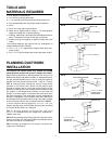
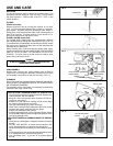
DAMPER/DUCT CONNECTOR (F30WV HOOD ONLY)
HINGE
PINS
DUCT
KNOCKOUTS
PREPARE THE HOOD
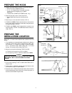
1. Unpack hood and check contents. You should receive:
1 -Aluminum Filter (F30WV hood only)
1 -3-1/4" x 10" Damper/Duct Connector (mounted
inside of hood for shipping only) (F30WV
hood only)
1 - Ductree filter (F24WR and F30WR hoods only)
2. Remove wiring box cover. Under cover find:
1 -Plastic Bag containing loose mounting hard-
ware
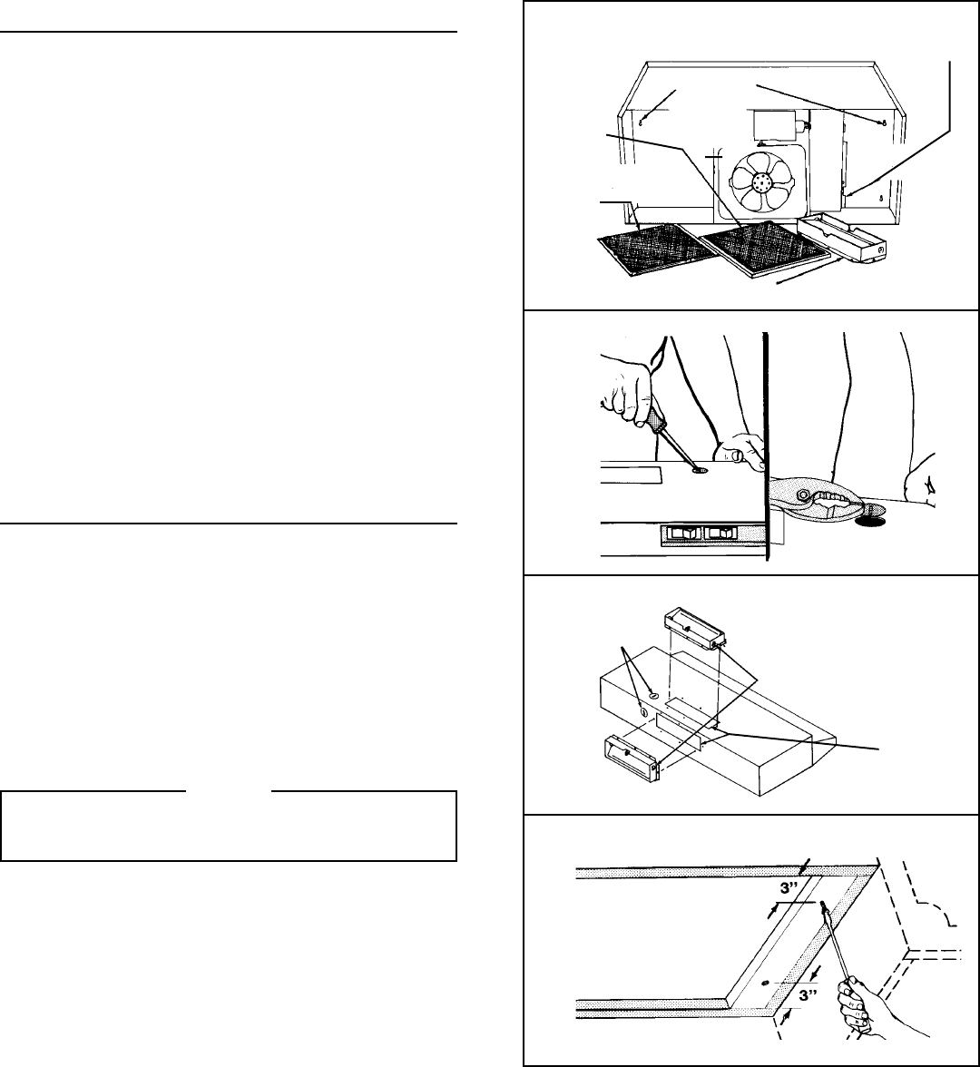
3. Remove top or rear electrical knockout. (FIG. 2)
4. (F30WV hood ONLY) Remove duct knockout. Insert screw-
driver under edge of knockout, break tabs, and peel knock-
out back with pliers. (FIG. 3)
5. (F30WV hood ONLY) Install damper/duct connector over
opening made in STEP 4. Use #8B sheet metal screws pro-
vided. (FIG. 3)
FIG. 1
FIG. 2
FIG. 3
FIG. 4
WIRING BOX COVER
DUCTFREE
FILTER
(F24WR &
F30WR
HOOD
ONLY
)
ALUMINUM
FILTER
(F30WV
HOOD
ONLY)
KEYHOLE
SLOTS
PREPARE THE
INSTALLATION LOCATION
Omit STEP 1 if hood will be installed under cabinets with flush
bottom.
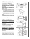
1. (For installation on recessed bottom cabinets only) Attach a
wood filler strip at each side of recessed area under cabi-
net. Use two 1" x 2" strips cut to length. If recess is deeper
than 1" use thicker strips. Attach strips with 1-1/4" wood
screws, 3" from each end of strip. See FIG. 4.
2. Measure and mark the following (FIGS. 5A & 5B):
a.) Electrical wiring opening in wall or cabinet.
b.) Duct opening in wall or cabinet (F30WV hood ONLY).
WARNING
WHEN CUTTING OR DRILLING INTO WALL OR CABINET,
BE CAREFUL NOT TO CUT EXISTING ELECTRICAL
WIRING.
3. Use 1-1/4" bit to drill opening for electric wiring.
4. Cut out duct opening in wall or cabinet with saber saw or
keyhole saw.
5. Center hood in installation opening and trace keyhole slots
onto wood filler strips on cabinet bottom.
6. Screw four #10 x 7/8 wood screws into exact center of narrow
end of traced keyhole slots. Allow 3/8" of screws to project, so
that hood can be fitted into place later.
ELECTRICAL
KNOCKOUTS


