7
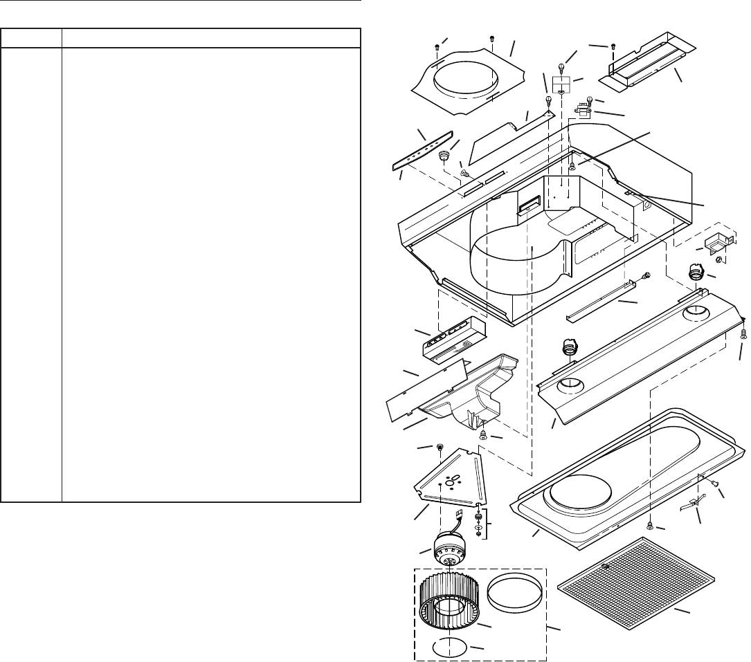
SERVICE PARTS
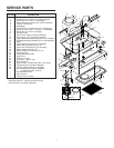
KEY NO. DESCRIPTION
1 7” Round Duct Plate (includes hardware)
2 Damper/Duct Connector (includes hardware)
3 Screw, #8-18 x ¼ Hex* (2 in package)
4 Motor Capacitor (includes wire nuts & hardware)
5 Isolation Transformer
6 Nameplate
7 Control Panel (includes Key No. 6 & hardware)
8 Screw for Plastic, #6 x ½ Flat Hd. (3 in package)
9 Screw, #8-18 x 3/8 (2 in package)
10 Ground Screw
11 Scroll Cover, Outlet (includes hardware)
12 Scroll Cover, Front (includes hardware)
13
Control Assembly (includes Key Nos. 6, 7 & hardware)
14
Air Chute Assembly (includes Key No. 15 & hardware)
15 Baffle
16 Screw, Metric M4 x 6mm (4 in package)
17 Motor Plate (Includes Key No. 18)
18 Motor Plate Mounting Kit (3 of each part)
19 Motor (includes Key No. 16)
20 Blower Wheel (Includes Key No. 21)
21 Retaining Ring
22 Lamp Socket Assembly
23 Light Panel
24 Hole Plug (1 req.)
25 Pop Rivet, .125D (3 req.)
26 Filter Spring Kit
27 Bottom Cover (includes Key Nos. 9, 25, & 26)
28 Autotransformer (includes hardware)
29 Aluminum Mesh Filter (2 in package)
30 Non-Ducted Blower Wheel Assembly
(includes Key Nos. 20 & 21)
** Non-ducted Filter Kit
** Wire Harness
** Control Fuse, 10-Amp
Order replacement parts by KEY NO.
* Standard hardware - may be purchased locally.
** Not illustrated - purchase separately.
1
2
5
6
8
10
11
7
16
9
4
17
19
3
3
12
13
14
3
21
22
23
9
9
26
9
27
29
3
18
28
24
20
9
15
30


