


7-8
12. Remove the top-connecting strip that covers the joint with the adjacent frypot.
13. Unscrew the Teflon vent/vacuum-breaker tube fitting, unscrew the nut located on the front of
each section of drain tube, and remove the tube assembly from the fryer.
14. Remove the covers from the drain safety switch(es) and disconnect the switch wiring at the
switch(es).
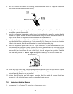
15. At the rear of the fryer, unplug the 12-pin connector C-6 and, using a pin pusher, disconnect the
high-limit thermostat leads.
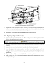
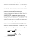
16. Disconnect the oil return flexline(s) at the frypot end(s).
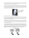
17. Raise the elements to the “up” position and disconnect the element springs.
18. Remove the machine screws and nuts that secure the element tube assembly to the frypot.
Carefully lift the element assembly from the frypot and secure it to the cross brace on the rear of
the fryer with wire ties or tape.
19. Carefully lift the frypot from the fryer and place it upside down on a stable work surface.
20. Recover the drain valve(s), oil return flexline connection fitting(s), and high-limit thermostat(s)
from the frypot. Clean threads and apply Loctite
™
PST 567 or equivalent sealant to the threads
of the recovered parts and install them in the replacement frypot.
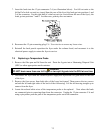
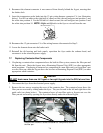
21. Carefully lower the replacement frypot into the fryer. Reinstall the hex head screw removed in
step 7 to attach the frypot to the fryer.
22. Position the element tube assembly in the frypot and reinstall the machine screws and nuts
removed in step 14.
23. Reconnect the oil return flexlines to the frypot, and replace aluminum tape, if necessary, to
secure heater strips to the flexlines.
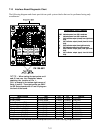
24. Insert the high-limit thermostat leads disconnected in step 13 (see illustration on page 1-3 for pin
positions).
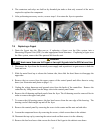
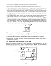
25. Reconnect the drain safety switch wiring to the switch(es) in accordance with the diagram below
then reinstall the switch covers.
ORANGE Pin 15 J4
BLUE Pin 1 C6
RIGHT
DRAIN SAFETY SWITCH
LEFT
DRAIN SAFETY SWITCH
(DUAL-VAT ONLY)
ORANGE Pin 7 J4
BLUE Pin 7 C6
NC
NO
COM
NC
NO
COM
26. Reinstall the drain tube assembly.