


v
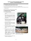
Master Jet CF Series Atmospheric Gas Fryers
TABLE OF CONTENTS (cont.)
PAGE #
1.12.6
2.
2.1
2.2
2.3
2.3.1
2.3.2
2.4
2.5
2.5.1
2.5.2
2.5.3
2.6
2.7
2.7.1.1
2.7.1.2
2.7.2
2.7.3
2.7.4
2.7.5
2.7.6
2.7.7
2.7.8.1
2.7.8.2
2.7.9
2.8
2.9
A.
A.1
A.1.1
A.1.2
A.1.3
A.1.4
A.1.5
A.1.6
A.1.7
A.2
Filter Magic II Wiring Diagram
PARTS LIST
Accessories
Burner Manifold Components
Cabinetry Components
Fryer Cabinetry
Filter Magic II and Spreader Cabinet Cabinetry
Casters, Legs and Associated Hardware
Component Shield, Filter Box Assemblies and Components
Component Shield Assemblies – No Interface Board
Component Shield Assemblies – With Interface Board
Filter Box Assemblies
Control Panel Assemblies and Related Components
Filtration System Components
Filter Magic II Drain Manifold Components
Euro-Look Drain Manifold Components
Filter Magic II Filter Pan Components – Outer Pan Components
Filter Magic II Filter Pan Components – Inner Pan Components
Oil Return Handle Components – Units Built Prior to April 2001
Oil Return Handle Components – Units Built April 2001 and After
Oil Return Plumbing
Filter Pump and Motor Components
Drain Valves and Related Components
Euro-Look Drain Valves and Related Components
Power Shower Components
Frypot, High-Limit and Probe Components
Wiring Connectors, Pin Terminals and Power Cords
APPENDIX
KJ3FC & J3F Variants – Wiring Diagrams
Computer Wiring Diagram – KJ3FC Fast-Ready
J3F Wiring Diagram – (Fast/Fast-Computer Modified; For Reference Only)
KFC-1 Computer Wiring Diagram – 120V
KFC-1 Computer Wiring Diagram – 220V
KSCF Wiring Diagram w/ Float (CE)
KFC-1 Harness Diagram
Transformer/Filter Box Wiring for FAST Controller
Parts List – KJ3FC Variant
1–40
2–1
2–1
2–3
2–5
2–5
2–7
2–9
2–10
2–10
2–11
2–12
2–13
2–15
2–15
2–17
2–18
2–19
2–21
2–22
2–23
2–24
2–26
2–27
2–28
2–29
2–31
A–1
A–1
A–1
A–2
A–3
A–4
A–5
A–6
A–7
A–8