


Part # 1844061 (08/06) Page 7
INSTALLATION
Rating Plate
When corresponding with the factory or your local
authorized factory service center regarding service
problems or replacement parts, be sure to refer to the
particular unit by the correct model number (including
the prefix and suffix letters and numbers) and the
warranty serial number. e rating plate affixed to the
rear of the oven contains this information.
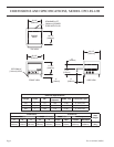
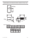
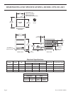
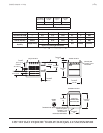
Clearances and Setting
Minimum Clearance for Installation.
Combustible to Non-Combustible Wall Clearance:
Side: 1” (25 mm)
Rear: 1” (25 mm)
Proper placement of the oven will ensure operator
convenience and satisfactory performance.
NOTE: Adequate clearance must be provided for
servicing and proper operation.
Location
Due to the heat a counter-top oven may produce, it must
be placed on a non-combustible surface. Do not store
combustible materials on top of any oven.
Electrical Connections
An all pole disconnect must be provided by the
installer.
Make sure electrical supply corresponds with that
specified on the rating plate located in the rear of the
oven.
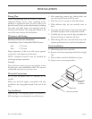
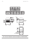
Leg Instillation
Optional legs – for shipping purposes the optional ”
( mm) legs are not mounted to any of the ovens.
1. After unpacking, remove legs, baking decks and
any other material from inside the oven.
2. Place the unit on a counter or other flat surface.
3. With sufficient help, tilt unit carefully onto its
back.
4. Screw legs into the bottom of the unit using holes
provided and tighten with an adjustable wrench.
5. Carefully tilt oven up onto the legs and adjust the
bottom of the legs to make the unit level.
6. Slide baking deck into each shelf and secure with
stainless steel hearth trim. (See Deck Installation)
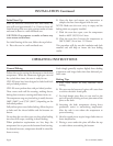
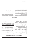
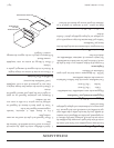
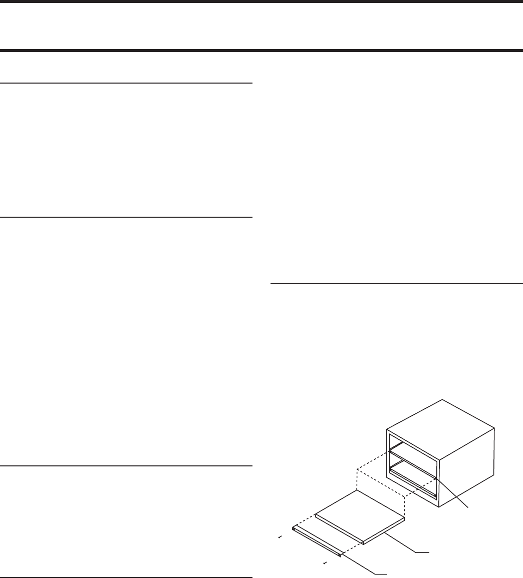
Deck Installation
A. Slide baking decks into each shelf.
B. Remove screw from mounting bracket left and right
side.
C. Place stainless steel (deck hold down) in place.
D. Fasten screws to mounting bracket.
MOUNTING
SCREW
LOCATION
DECK
DECK HOLD DOWN