


Part # 1009080 Rev 5 (01/25/08) Page 7
INSTALLATION
Unpacking
Unpack units carefully and provide the necessary space on
counter of back bar. All units must be installed following the
minimum back and side clearances stated on the tag axed
to each individual unit. To insure proper eld wiring size
check tag attached to the rear of the unit near knockout.
Leg Installation
1. All units are shipped with N.S.F. approved legs. These
legs must be installed to provide a minimum clearance
of 4” (102mm) between he counter top and bottom of
the appliance in order to meet the National Sanitation
Foundation requirements.
2. When using the legs described above, raise the front of
the appliance and screw the leg into the leg-retaining nut
provided at each corner of the appliance, repeat at each
rear.
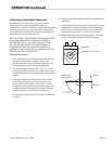
3. The unit may be leveled by adjusting the legs. Use a spirit
level and level the appliance four (4) ways: across the
front and back; and down left and right edges.
NOTE: Griddles may not rest evenly on the appliance body if
the appliances are not leveled.
Electrical Connections
Before attempting the electrical connection, the rating
plate should be checked to ensure that the unit’s electrical
characteristics and the supply characteristics agree.
Installation of the wiring must be made in accordance with
UL 197 Commercial Electric Cooking Appliance Standards,
Local and/or National Electrical Code, and ANSI/NFPA 70-
1990 and include.
1. Switch panel size
2. Overload protection
3. Wire type
4. Wire size
5. Temperature limitations of the wires
6. Method of connection (Cable, Conduit, etc.)
The service line enters though the rear of the unit and is
to be connected to the terminal block. Input voltage and
phasing must match the unit’s voltage and phasing.
Visually check all electrical connections.
Energize the electrical connections.
NOTE: Appliances are not internally fused. They must be
connected to a suitable disconnect box in accordance with
local code.
E24-12H Hot Plate
Electrical connection to the terminal may be made though
the knockout on the main back. Front access is gained by
raising the rear surface element and removing bowl. The
terminal block shield is located toward the back lower left of
the unit.
E24 Series Griddles
The electrical connections may be made though the
knockout at the rear of the unit to the terminal block located
behind the terminal block shield.
Front access is gained by raising and propping the griddle
plate. The terminal block shield is toward the back and left
of the appliance. Remove the shield to expose the terminal
block. Make the necessary connection and replace the shield.
These appliances have no fusing.