


15
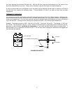
CHECK GROUNDING
A common ground is required for the pilot burner, the ignitor-sensor, the GND terminal of the S86, and the main
burner. The main burner generally serves as the common ground. If the ground is poor or erratic, safety shutdowns
may occur occasionally even though operation is normal at the time of the checkout. Therefore, if nuisance
shutdowns have been reported, be sure to check the grounding.
NOTE: If the ground circuit path is incomplete, the S86H system control will allow one trial-for-ignition
before going into safety lockout.
Electrical grounding connections at the pilot burner, ignitor/sensor and S86 must be clean and tight. If lead wire is
damaged or deteriorated, use only No. 14 of 18 gauge, moisture-resistant, thermoplastic insulated wire with 105°C.
(221°F) minimum rating as replacement. Excessive temperature at the ceramic flame rod insulator can also permit
electrical leakage to ground. Examine the flame rod and mounting bracket, and correct if bent out of position.
Replace ignitor/sensor of insulator is cracked.
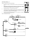
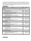
CHECK SPARK IGNITION CIRCUIT
The electronic module and step-up transformer in the S86 provides spark ignition at 15,000 Volts (open circuit). This
circuit can be checked at the S86 module as follows:
1. Turn off the manual gas cock to prevent the flow of gas.
2. Disconnect the ignition cable at the S86 stud terminal to isolate the circuit from the pilot burner/ignitor/sensor, and
prepare a short jumper lead using heavily insulated wire, such as ignition cable.
3. Energize the S86. Touch one end of the jumper firmly to the S86 ground terminal (GND). Do not disconnect the
existing ground lead. Move the free end slowly toward the stud terminal to establish a spark and then pull the
lead wire slowly away from the stud. Note the length of the gap at which arcing stops.
CAUTION: Do not touch either stripped end of jumper or stud terminal. This is a very high voltage circuit
and electrical shock can result. Perform the test immediately upon energizing the system -
before the S86H goes into safety lockout and interrupts the spark circuit.
4. An arc length of 1/8" (3.2 mm) or more indicates satisfactory voltage output. Replace the S86 if no arc can be
established or the maximum gap is less than 1/8" (3.2 mm), and the fuse and power to the S86 input terminal
was okay.
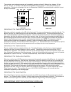
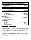
CONTROL MODULE FLAME SENSOR CIRCUIT
The control module provides AC power to the ignitor/sensor which the pilot burner flame rectifies to direct current. If
the flame signal back to the control module is not at least 1.0 µA DC, the system will lockout. The output of the flame
sensing circuit cannot be checked directly, so check the flame sensing circuit indirectly by checking the flame sensing
current from the ignitor/sensor to the control module as follows:
1. Connect a meter (DC micrometer scale) in series with the flame signal ground wire (Burner Ground Terminal).
Disconnect the ground wire at the control module. Connect the red (positive) lead of the meter to the free end of
the ground wire. Connect the black (negative) meter lead to the quick-connect ground terminal on the control
module.
2. Restart the system and read the meter. The flame sensor current must be at least 1.0 µA, and the reading must
be steady. If the reading is below the value designated or the reading is unsteady, check the pilot flame and
electrical connections as described above. Also, replace the ignitor/sensor if the ceramic insulator is cracked.
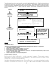
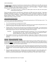
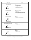
EXAMPLES OF UNSATISFACTORY PILOT FLAMES