


Part # 1382684 Rev. 1 (02/11/11) Page 7
Gas Supply
Before assembly and connection check the gas supply.
1. The type of gas for which the unit is equipped is stamped
on the data plate located behind the drip tray. Connect
a unit stamped “NAT” only to natural gas; connect those
stamped “PRO” only to propane gas.
2. If it is a new installation have the gas authorities check
the meter size and piping to assure that the unit is
supplied with sucient amount of gas pressure required
to operate the unit.
3. If it is an additional or replacement equipment have the
gas authorities check the pressure to make certain that
the existing meter and piping will supply fuel to the unit
with not more than 1/2” water column pressure drop.
WARNING: Check gas connections for leaks. Use a soap
solution or similar means. DO NOT USE AN OPEN FLAME.
NOTE: This appliance is not recommended for residential
installation.
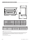
Ventilation and Air Supply
Proper ventilation is highly important for good operation.
The ideal method of ventilation for a Salamander broiler is
the use of a properly designed canopy hood, which should
extend six (6”, 152 mm) beyond all sides of the appliance and
six (6) feet six (6) inches (1981 mm) from the oor.
A strong exhaust fan will create a vacuum in the room. For an
exhaust system to work properly, replacement air must enter
the room in which the vent is located. The amount of air that
is exhausted must equal the amount entering, (make-up air).
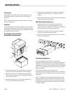
INSTALLATION continued
All gas burners and pilots need sucient air to operate and
large objects should not be placed in front or on the top of
the broiler, which would obstruct the airow though, the
front of the broiler.
For your safety NEVER place any type of object on top of
the salamander broiler or cheese meters. The top of the
broiler will exceed 1000°F. It could cause severe burns or
re and obstruct ventilation.
Testing And Adjustments
All ttings and pipe connections must be tested for leaks.
Use approved gas leak detectors, soap solution or equivalent,
checking over and around the ttings and pipe connections.
DO NOT USE A FLAME! Accessibility to all gas lines and
ttings require that valve panel(s), lower front panel(s) be
removed. It may be necessary to remove or at least raise and
secure top grates. All parts removed (including fasteners)
should be stored safely for re-use.
Testing
1. Be sure all valves are in the “OFF” position
2. Turn on the main gas supply valve. Light all top section
pilots.
3. Leak test all valves and ttings as described in the
procedure above. Correct any leaks as required and
recheck.
4. Shut o all gas valves.
All units are tested and adjusted at the factory. However,
burners and pilots should be checked at installation and
adjusted if necessary.