


3
INSTALLATION INSTRUCTIONS
INSTALLATION
PR8178
1
M6 Screws
Velcro Pads
PR8179
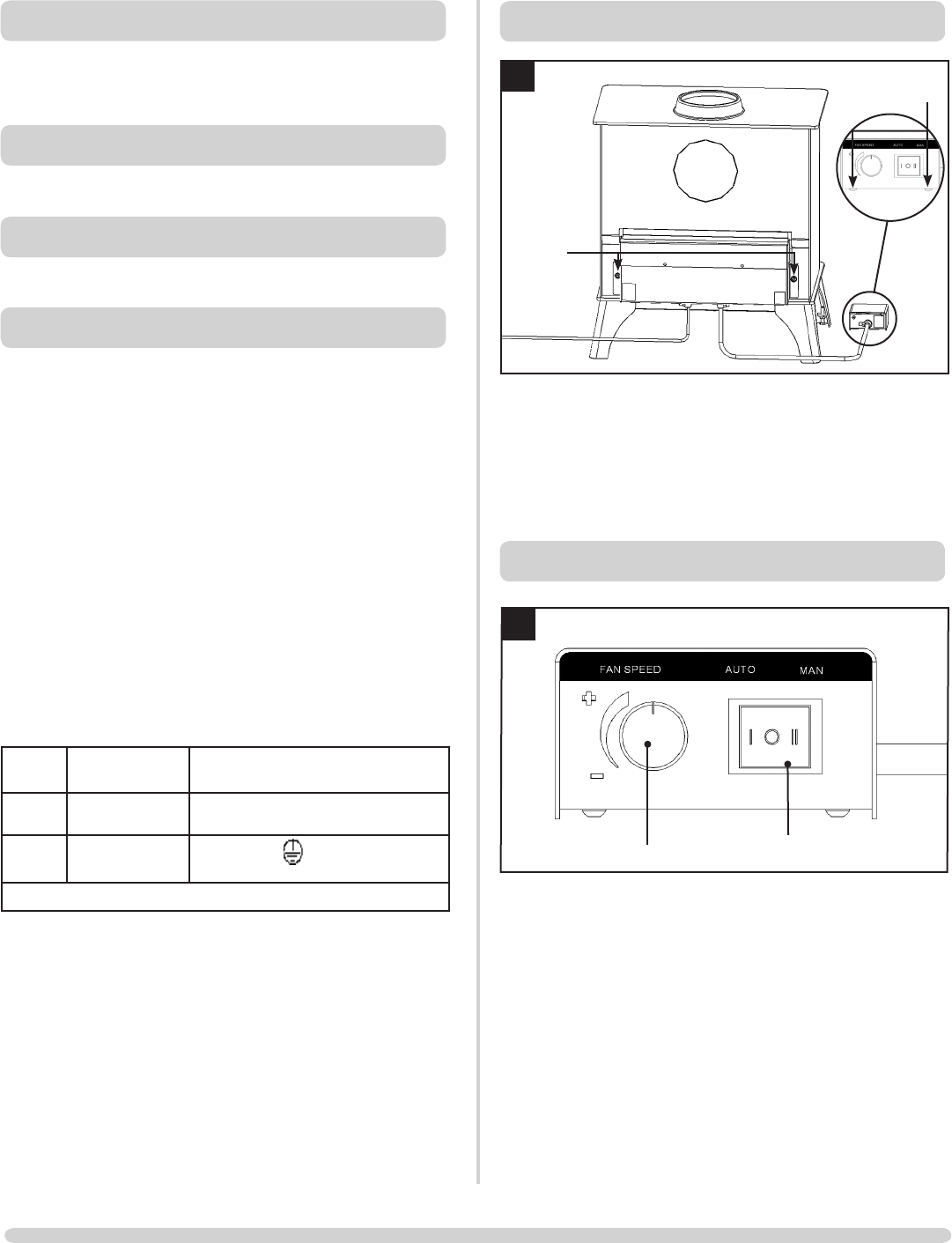
1.1 • Position Fan kit as shown, diagram 1
• Attach using M6 Nuts supplied
• Secure control box in a convenient place using the self
adhesive Velcro pads supplied
COMMISSIONING
PR8179
1
Speed control
3 way switch
1. Check operation of fan kit
2. Explain the use of all the controls to the customer
3. Store these instructions with the ones supplied with the cassette
GENERAL
This fan system may be supplied in kit form and installed
in accordance with these instructions OR it may have
been factory fitted.
PACKING LIST
• Riva Plus Fan Kit
TOOLS REQUIRED
• 10mm A/F Spanner
POWER SUPPLY
A 230v 50 - 60Hz supply is required.
THIS APPLIANCE MUST BE EARTHED
Provision for the power supply should be made before
installing the product, with connections made by a
qualified electrician via a 3 Amp supply and complying
with any local and national regulations and guidelines
• The appliance must be protect by a 3 amp fuse
• The electrical connection must allow for disconnection
• Use heat resistant cable
If the electricity supply cable is damaged do not use the
appliance until it has been replaced. For safety reasons the
replacement should be carried out by a Stovax servicing
agent or a similarly competent electrician.
Live
wire
Brown Terminal Marked L / coloured RED
Neutral
wire
Blue
Terminal Marked N / coloured
BLACK
Earth
wire
Green and
yellow stripes
Marked E / / colour GREEN or
GREEN & YELLOW
230v 50 - 60Hz supply is required
WARNING – FAILURE TO CONNECT THE WIRES CORRECTLY
COULD PUT PEOPLE AT RISK FROM ELECTRIC SHOCK OR
FIRE.