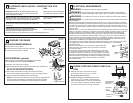
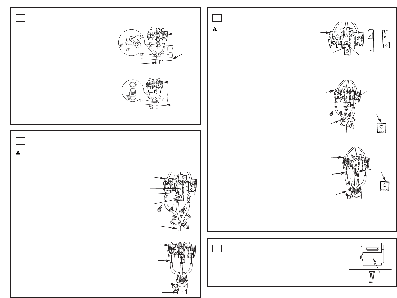
3-WIRE INSTALLATION
WARNING:
The neutral or ground wire of the power cord must be connected
to the neutral terminal located in the center of the terminal block. Ground strap must connect
the neutral teminal to the ground plate. The power leads must be connected to the lower
left and the lower right terminals of the terminal block.
DO NOT remove the ground strap connection.
FOR POWER CORD INSTALLATION
A. Remove the 3 lower terminal screws from the terminal block.
B. Insert the 3 terminal screws through each power cord termi-
nal ring and into the lower terminals of the terminal block. Be
certain that the center wire (white/neutral)
is connected to the center lower position of the terminal
block.
C. Tighten screws securely into the terminal block.
FOR CONDUIT INSTALLATION
A. Loosen the 3 lower terminal screws from the terminal block.
B. Strip wire to expose tip about 5/8" long. Insert the center
(white/neutral) wire tip through the bottom center terminal block opening. On
certain models, the wire will need to be inserted
through the ground strap opening and then into the bottom
center block opening. Insert the two side bare wire tips into
the lower left and the lower right terminal block openings.
C. Tighten screws until the wire is firmly secured (35 to 50 inch-lbs.).
Do not over-tighten the screws.
NOTE: ALUMINUM WIRING: Aluminum building wire may
be used but it must be rated for the correct amperage and voltage.
PROCEED TO STEP 9.
7
Ground
strap
Terminal block
(appearance
may vary)
Neutral
terminal
Power cord
Ground
plate
Power Cord
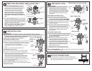
4-WIRE INSTALLATION
WARNING:
The neutral wire of the supply
circuit must be connected to the neutral terminal
located in the lower center of the terminal block.
The power leads must be connected to the lower
left and the lower right terminals of the terminal block.
The grounding lead must be connected to the frame
of the range with the ground plate and the green
ground screw.
FOR POWER CORD INSTALLATION
A. Remove the 3 lower terminal screws from
the terminal block. Remove the ground screw
and ground plate and retain them. Cut and discard
the ground strap. DO NOT DISCARDANY SCREWS.
B. Insert the one ground screw into the power cord ground
wire terminal ring, through the ground plate and into
the frame of the range.
C. Insert the 3 terminal screws (removed earlier) through
each power cord terminal ring and into the lower terminals
of the terminal block. Be certain that the center wire
(white/neutral) is connected to the center lower position
of the terminal block. Tighten screws securely into
the terminal block.
FOR CONDUIT INSTALLATION
A. Loosen the 3 lower terminal screws from the terminal block.
Remove the ground screw and ground plate and retain
them. Cut and discard the ground strap. DO NOT
DISCARD ANY SCREWS.
B. Strip the wire to expose tip about 5/8" long. Insert
the ground bare wire tip between the range frame
and the ground plate (removed earlier) and secure
it in place with the ground screw (removed earlier).
Insert the bare wire (white/neutral) tip through the bottom
center of the terminal block opening. Insert the two
side bare wire tips into the lower left and the lower
right terminal block openings.
C. Tighten the screws until the wire is firmly secured
(35 to 50 inch-lbs.). Do not over-tighten the screws.
NOTE: ALUMINUM WIRING: Aluminum building wire may be used but it must be rated
for the correct amperage and voltage.
8
Before–Power Cord and Conduit
Terminal
block
Terminal
block
Neutral termi-
nal
Neutral
terminal
Ground
strap
Ground plate
(grounding to
range)
Ground
screw
Ground strap
or
After–Conduit
Terminal
block
Ground
plate
(grounding
to range)
Wire
tips
Ground screw
After–Power Cord
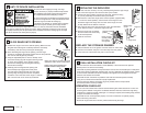
REPLACE THE WIRE COVER
Replace wire cover on range back by sliding its left edge under
the retaining tabs and replace the screws removed earlier. Make sure
that no wires are pinched between cover and range back.
9
POWER CORD AND CONDUIT INSTALLATION (CONT.)
C. For power cord installations only (see the next
step if using conduit), assemble the strain relief
in the hole. Insert the power cord through the strain
relief and tighten. Allow enough slack to easily
attach the cord terminals to the terminal block.
If tabs are present at the end of the winged
strain relief, they can be removed for a better fit.
NOTE: Do not install the power cord without a
strain relief. The strain relief bracket MUST be
installed before reinstalling the rear range wiring
cover.
D. For conduit installations only, purchase a squeeze
connector matching the diameter of your conduit and
assemble it in the hole. Insert the conduit through the
squeeze connector and tighten. Allow enough slack to eas-
ily attach the wires to the terminal block.
NOTE: Do not install the conduit without a squeeze con-
nector. The squeeze connector MUST be installed
before reinstalling the rear range wiring cover.
6
Power cord
Strain relief
Terminal
block
Bracket
Squeeze connector
Terminal
block
Bracket
Wire
cover
Wire tips
Terminal
block
Conduit
Conduit