


9
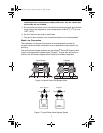
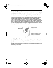
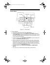
Overflow Line Connection
In the absence of a safety overflow and in the event of a malfunction, the BRINE
TANK OVERFLOW will direct “overflow” to the drain instead of spilling on the floor
where it could cause considerable damage. This fitting should be on the side of
the cabinet or brine tank.
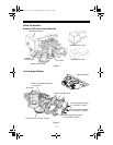
To connect overflow, locate hole on side of brine tank. Insert overflow fitting (not
supplied) into tank and tighten with plastic thumb nut and gasket as shown
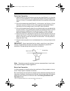
(Figure 7). Attach length of 1/2-inch (1.3-cm) I.D. tubing (not supplied) to fitting
and run to drain. Do not elevate overflow line higher than 3 inches (7.6 cm) below
bottom of overflow fitting. Do not tie into drain line of control unit. Overflow line
must be a direct, separate line from overflow fitting to drain, sewer or tub. Allow an
air gap as per drain line instructions (Figure 6).
Figure 7
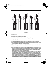
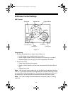
Low Voltage Transformer
Use only the included transformer for powering the 400 series timers. Connect the
plug of the transformer secondary cable to the mating socket on the control (see
Figure 8).
Be certain that the transformer is plugged into a correct voltage source that is not
controlled by a wall switch.
Brine Tank
Overflow Fitting
Installed
Connect 1/2-inch (1.3-cm)
Tubing or Hose and Run
to Drain
1018075 Rev I.fm Page 9 Tuesday, February 17, 2004 4:26 PM