


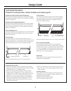
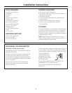
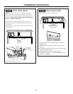

36" Frame to
Frame Width
*84" From
Floor to
Top Frame
35"
Case Width
*83-1/2"
at
Rear
25-3/8" Framed Models
25-3/4" Stainless Steel Models
Case Depth
Depth Including Handles:
26-7/8" Framed Models
27-3/4" Stainless Steel Models
28-11/16" Professional Style Models
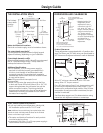
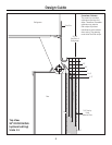
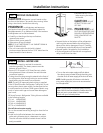
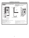
THE INSTALLATION SPACE
Water And Electrical Locations
Electrical and water supply must be located as shown.
The cutout depth must be 24″
The refrigerator will project forward, slightly beyond
adjacent cabinetry, depending on your installation.
Cutout depth beneath a soffit:
When installed beneath a soffit, the soffit cannot exceed
the 24″ installation depth shown. The top case trim
overlaps the bottom of the soffit.
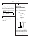
Additional Specifications
• A 115 volt 60Hz., 15 or 20 amp power supply is
required. An individual properly grounded branch
circuit or circuit breaker is recommended. Install
a properly grounded 3-prong electrical receptacle
recessed into the back wall. Electrical must be located
on rear wall as shown.
Note: GFI (ground fault interrupter) is not
recommended.
• Water line can enter the opening through the floor
or back wall. Route GE SmartConnect
™
kit or 1/4″ O.D.
copper tubing between the cold water line and the
water connection location. The tubing should be
long enough to extend to the front of the refrigerator.
Installation of an easily accessible shut-off valve in
the water line is required.
DIMENSIONS AND CLEARANCES
* Shipping height. The
refrigerator can be
adjusted to fit into a
cutout that is 83-1/2
″
min. to 84-1/2″ max.
height. Note that the top
case trim at the front is
1/2
″ higher and will
overlap upper cabinetry
or soffit. Use leveling legs
and wheels for a
maximum 1
″ height
adjustment.
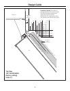
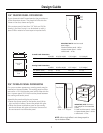
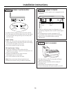
Product Clearances
These refrigerators are equipped with a 2-position door
stop. The factory set 130° door swing can be adjusted to
90° if clearance to adjacent cabinets or walls is restricted.
3
6"
Wall View
Electrical
Area
84-1/2" max
83-1/2" min
Finished
Opening
75" From
Floor to
Bottom
of Electrical Area
10"
24" Cutout Depth
35-1/2"
Finished Width
2-5/16"
5"
10"
10"
3-1/2" 3-1/2"
5"
3-1/2"
Water Supply
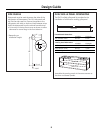
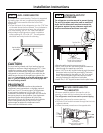
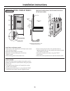
ZUG2, ZUGSS2 Unified Grille Panel Kit
• If you are installing two refrigerators, side by side,
the installation space must be 71-1/2″ wide.
Note: Additional cutout width may be required when side
panels are used. Add side panel thickness to the finished
cutout to calculate rough-in width.
• The water and electrical locations for each product
must be located as shown.
• A separate 115V, 60Hz., 15 or 20 amp power supply is
recommended for each product.
2-5/16"
75" From
Floor to Bottom
of Electrical Area
84-1/2" max
83-1/2" min
Finished
Opening
71-1/2" Finished Width
Electrical
24" Cutout Depth
Wall View
24-3/16"
6"
10"
6"
10"
5"
10"
10"
Water Supply
3-1/2" 3-1/2" 3-1/2" 3-1/2"
5"
3-1/2"
5"
10"
5"
3-1/2"
The finished
cutout width
must be
35-1/2″.
Allow 25″ minimum clearance for a full 130° door
swing. Allow 15″ for pan removal.
For a 90° door swing, allow 4″ min. clearance to a wall,
for framed and stainless steel models. Allow 5″ min.
clearance for professional style models. If the 90° door
stop position is used, pan access is maintained, but pan
removal is restricted.
See illustrations pages 4 and 5 to determine door swing
interaction with adjacent cabinets or countertops.
Design Guide