


35
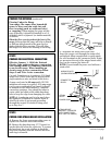
C. Assemble the strain relief in the hole.
Insert the power cord through the strain relief
and tighten. Allow enough slack to easily attach
the cord terminals to the connector block. If tabs
are present at the end of the winged strain relief,
they can be removed for better fit.
NOTE: Do not install the power cord without a
strain relief.
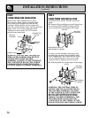
PREPARE THE OPENING (continued)
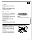
Flooring Under the Range
Your range, like many other household
items, is heavy and can settle into soft
floor coverings such as cushioned vinyl
or carpeting. When moving the range on this
type of flooring, it should be installed on a 1/4
inch thick sheet of plywood (or similar material)
as follows:
When the floor covering ends at the front of the
range,
the area that the range will rest on should
be built up with plywood to the same level or
higher than the floor covering. This will allow
the range to be moved for cleaning or servicing.
STEP 2
PREPARE FOR ELECTRICAL CONNECTION
Effective January 1, 1996 the National
Electric Code requires that new construction
(not existing) utilize a 4 conductor connection
to an electric range. When installing an
electric range in new construction follow
Steps 3 and 5 for 4 wire connection.
Use only 3-conductor or 4-conductor U.L. listed
range cord. These cords may be provided with
ring terminals on wire and strain relief device.
A range cord rated at 40 amps with 125/250
minimum volt range is required. A 50 amp range
cord is not recommended but if used, it should
be marked for use with nominal 1
3
⁄
8
″ diameter
connection openings. Care should be taken to
center cable and strain relief within knockout
hole to keep the edge from damaging the cable.
NOTE: A 4-conductor cord is to be used when
the appliance is installed in a mobile home or
when local codes do not permit grounding
through the neutral. If conduit is being used,
go to Step 6 or 7.
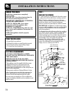
STEP 3
POWER CORD STRAIN RELIEF INSTALLATION
A. Remove the lower rear range wiring cover to
expose the connector block and bracket.
B. Remove the knockout ring (1
3
⁄
8
″) located on
bracket directly below the connector. To remove
the knockout, use a pair of pliers to bend the
knockout ring away from the bracket and twist
until ring is removed.
(continued next page)
STRAIN RELIEF
BRACKET (PROVIDED
WITH RANGE CORD.
NOT PART OF RANGE.)
BEFORE
AFTER
BRACKET
CONNECTOR
BLOCK
WIRING COVER
(SHOWN REMOVED)
STRAIN
RELIEF
POWER CORD
GROUND
STRAP
KNOCKOUT
RING
REMOVED
KNOCKOUT
RING
BRACKET