


Installation Instructions
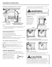
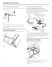
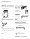
STEP 2 ADJUST LEVELING LEGS
• Move the dishwasher close to the installation location and lay
it on its back.
Figure I
• Measure installation height and dishwasher height. Extend
leveling legs out from the dishwasher base, 1/2" less than
installation height.
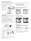
STEP 3 REMOVE TOEKICK
• Remove the 4 toekick screws. Lift off the 2 piece toekick.
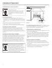
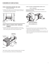
STEP 4 INSTALL POWER CORD
Skip this step if dishwasher will be direct wired.
Use Power Cord Kit WX09X70910, available for purchase
from an authorized GE Appliance Dealer. The power cord and
connections must comply with the National Electrical Code,
Section 422 and/or local codes and ordinances.
• Maximum power cord length is 6'.
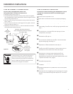
• Connect incoming power cord white (or ribbed) to dishwasher
white, black (or smooth) to black and ground to dishwasher
green wire. Use UL listed wire nuts of appropriate size.
• Replace junction box cover. Be sure wires are not pinched
under the cover.
Figure K
Figure J
Figure L
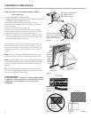
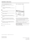
STEP 5 INSTALL 90° ELBOW
• Wrap 90° elbow with thread seal tape.
• Install a 90° elbow onto the water valve.
• Do not over tighten 90° elbow, water valve bracket could
bend or water valve fi tting could break.
• Position the end of the elbow to face the rear of the
dishwasher.
6
Adjust to
Installation
Height
Remove
4 Toekick
Screws
White
Ground
Black
Check That White, Black and
Green Dishwasher Wires Are Threaded
Thru Hole in Back
Remove
Junction Box
Cover
Insert Power
Cord Wires Thru
Strain Relief
and Tighten
Use UL Listed
Wire Nuts
A
C
B
D
90°
Elbow
Fill
Hose
Thread
Seal Tape
Wa
ter
Va
lve
Bracket