


6
Installation Instruction
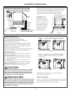
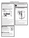
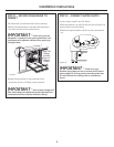
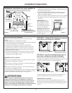
STEP 2 – ADJUST LEVELING LEGS
0RYHWKHGLVKZDVKHUFORVHWRWKHLQVWDOODWLRQ
location and lay it on its back.
0HDVXUHLQVWDOODWLRQKHLJKWDQGGLVKZDVKHUKHLJKW
Extend leveling legs out from the dishwasher base,
1/4”less than installation height.
Figure 8
Adjust to
Installation
Height
Adjust to
Installation
Height
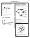
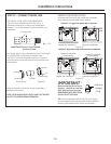
STEP 3 – REMOVE TOEKICK
5HPRYHWKHWRHNLFNVFUHZV/LIWRIIWKHSLHFH
toekick.
Figure
9
2-Screws
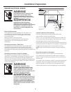
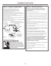
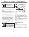
STEP 4 – INSTALL POWER CORD
Skip this step if dishwasher will be direct wired.
The power cord and connections must comply with
the National Electrical Code, Section 422and/or local
codes and ordinances.
Recommended power cord length is 54” min. and 64” max.
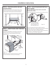
Connect incoming
power cord white (or ribbed)
to dishwasher white. Black
(or smooth) to black. Ground to dishwasher green
wire. Use UL listed wire nuts of appropriate size.
Replace junction box cover . Be sure wires are not
pinched under the cover .
White
Ground
Black
Check That White, Black and
Green Dishwasher Wires Are Threaded
Thru Hole in Back
Remove
Junction Box
Cover
Inser t Power
Cord Wires Thru
Strain Relief
and Tighten
Use UL Listed
Wire Nuts
A
C
B
D
Figure 10
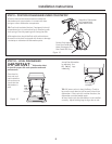
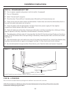
STEP 5 – INSTALL 90° ELBOW
Wrap 90 elbow with thread seal tape.
Install a 90 elbow onto the water valve.
'RQRWRYHU7LJKWHQHOERZZDWHUYDOYHEUDFNHW
could bend or water valve fitting could break.
3RVLWLRQWKHHQGRIWKHHOERZWRIDFHWKHUHDURIWKH
dishwasher .
Figure 11
90
Elbow
Fill
Hose
Threa d
SealTape
Water
Valve
Br acket