


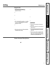

PREPARING FOR INSTALLATION
19
Installation Instructions
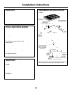
TOOLS AND PARTS NEEDED
• Large flat-blade screwdriver
• Saw
• Carpenter’s square
• Pipe wrench
• 7/16″ open end wrench
• Gas line shut off valve
• Pipe joint sealant for use with gas connections
For flexible connection where local
codes permit:
• Flexible metal tubing (same 3/4″ or 1/2″ I.D. as
gas supply line)
• Flare union adapter for connection to supply line
(3/4″ NPT x 3/4″ I.D. or 1/2″ NPT x 1/2″ I.D.)
• Flare union adapter for connection to regulator
(1/2″ NPT x 3/4″ I.D. or 1/2″ I.D.)
For rigid connection:
• Pipe fittings as required
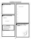
PARTS LIST
• Gas cooktop base unit
• Literature pack
• 1 Surface burner assembly
• 2 Surface burner grates
• 1 Vent filter
• 1 Vent grille
• 1 Grease jar
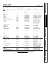
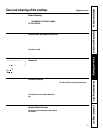
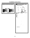
JGP979
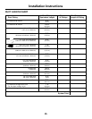
Tie down bolt
on each end
Select appropriate
duct cutout. (See
ducting installation
instructions.)
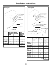
Appliance
Pressure
Regulator
Grease
Container
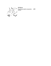
Grease Container
Pressure Regulator
Wiring Box Cover
28
7
⁄8″
1
⁄16″
*Blower can be
swiveled 90°
* Blower may be rotated for horizontal or vertical direction by loosening
nuts around blower inlet. Accessible inside ventilation chamber.
7
9
⁄16″
15
5
⁄8″
3
5
⁄16″
11
7
⁄8″
9
3
⁄8″
1
7
⁄8″ Min.
15
⁄16″
20
15
⁄16″
1
⁄16″
Minimum
Clearance
Minimum
Clearance
73.34 .16 cm
23.81 cm
2.38 cm
8.41 cm
39.69 cm
2″
30.16 cm
4.76 cm
19.21 cm
53.18 .16 cm
14″
35.56 cm
13″
33.02 cm
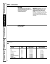
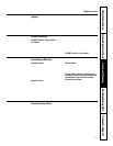
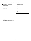
IMPORTANT
Motor Clearance—Provide 2″ min. (5.1 cm) cabinet
clearance to motor for cooling purpose.
NOTE: Where possible, 6″ (15.2 cm) is
recommended for motor/blower service.
Side Clearance—Grills installed near a side wall
should allow a minimum clearance of 8″ (20.3 cm).
You must allow room enough to remove and empty
grease container(s).
CAUTION: Warranty is void on equipment installed
other than as recommended by GE. Recommended
wall caps and transitions must be used for proper
operation and installation.
5.08 cm
Minimum
Clearance