


8
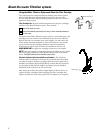
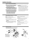
Electronic Faucet Installation (not available on all models)
Be sure there is room underneath the sink to make the needed
connections. Select one of the following places to install the faucet:
—IN an existing sink spray attachment or soap dispenser hole.
—IN a hole to be drilled in the sink top.
—IN a hole to be drilled in the countertop, next to the sink.
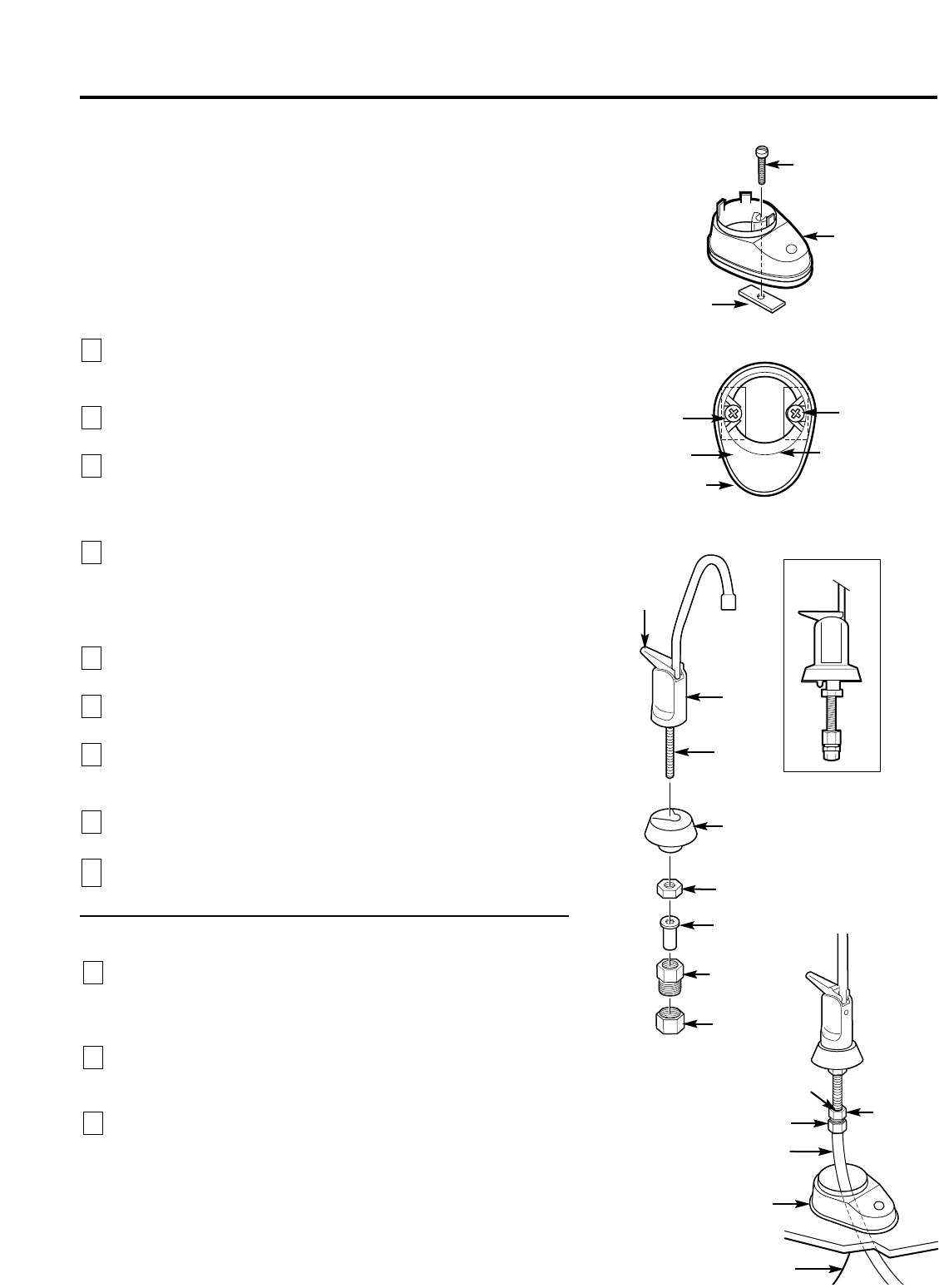
NOTE: Looking at fourth illustration at right, be sure the faucet base
will fit flat against the surface at the selected location so the gasket will
seal. The base may have to be angled sideways or diagonally.
If drilling is needed, make a 1″ – 1 1⁄4″ dia. hole. Be
sure to use the
proper procedure for drilling porcelain or stainless steel. Special drill
bits may be needed.
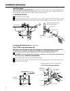
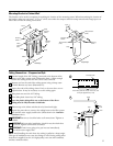
Looking at first illustration, insert a screw into the NON-SLOTTED
base mounting hole. Turn a flat nut a few turns onto the screw.
Position the base gasket over the mounting hole. Set the base on
the gasket, routing the leadwire through the mounting hole.
Holding the flat nut under the sink with one finger, tighten the
screw until just snug.
Turn the remaining flat nut a few turns onto the other screw.
Position the screw in the slotted base mounting hole and tighten
until snug. Make sure the gasket position is properly aligned and
carefully tighten both screws until the base is held firmly in place.
Do not overtighten and break the base.
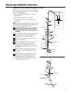
Assemble the top faucet base and hex nut onto the faucet stud
(third illustration). Tighten the nut until snug.
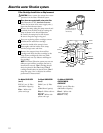
Insert tubing insert into tubing adapter. Securely tighten to faucet
stud.
Feed the length of 3/8″ OD tubing from the bottom up through
the faucet base. Connect to the tubing adapter as shown in fourth
illustration, tightening the compression nut securely.
Remove the short shipping tube and screw the spout into the
faucet body.
Lower the faucet assembly and lock into place on the faucet base.
9
8
7
6
5
4
3
2
1
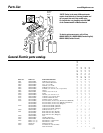
Faucet
base
Nut (2)
Screw (2)
1″– 1 1/4″ dia.
mounting hole
in sink or
countertop
Gasket
Faucet base
TOP VIEW
Screw (2)
Nut (2)
Base lead wire connector
(to battery pack)
3/8″ tubing, (run
to Filter 2 outlet)
Faucet base
Compression nut
Tubing insert
Hex nut
Top faucet
base
Faucet
Lever
Spout
Faucet stud
Compression nut
Tubing adapter
ASSEMBLED
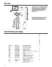
Step-by-step installation instructions.
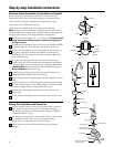
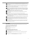
Battery Pack Installation and Connection
In a dry location, within reach of the electronic base 3′ lead wire,
select a place for the battery pack (see illustration on page 5).
The battery pack attaches to most surfaces, using the included
“sticky-back” Velcro™ strip.
The battery pack uses two size AA batteries. Check to be sure they
are installed correctly. Then, remove the paper backing
on the Velcro™ strip and secure the pack in place.
Fasten electronic base lead wire and battery pack connector
together.
3
2
1
Tubing insert
Tubing adapter