


15
Installation Instructions
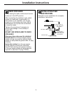
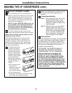
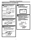
Units with 4 burners
Units with 5 burners
Install the LP/Propane orifices in their
precise locations as noted in the
illustrations above.
Return the natural gas orifices to the
bracket and reattach the bracket and
the instruction sheet to the pressure
regulator using the screw removed
previously.
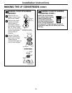
Replace the burner bases, heads, caps
and top grates. (NOTE:
When re-attaching
the bur
ner bases to glass top units,
tighten scr
ews to a maximum of
10 in.-lbs tor
que.)
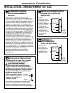
G
F
E
Left Front Right Front
Model Orifice Orifice
JGP630 II III
JGP963 III X
JGP970
ZGU36K
Replace: With:
JGP975 III Main 206X N ➔ 108X L
Simmer 57N ➔ 34L
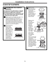
CHANGE COOKTOP BURNER
ORIFICES (CONT.)
Locate the LP/Propane orifices shipped
inside the literature package. They
will have a digit number and the letter
“L” on the side. (Important: Save the
orifices removed from the appliance
for future use.)
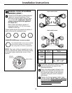
Each orifice will show a series of
engraved marks, (I, II, III, X or none),
located on the top.
These marks denote the precise location of
each orifice to the cooktop burner.
18,000 BTU/HR Burner (on some models)
NOTE: The main orifice is located low in the
center of the burner while the simmer orifice
is located higher behind the center of the
burner.
D
3
The 18,000 BTU/HR burner has two orifices
with markings located in the sides only.
(See rating plate on bottom of appliance).
I II III
X
Main orifice
Simmer
orifice