


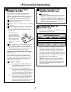

CHECK IGNITION
Connect electrical supply cord.
Turn on the gas; check for leaks using a liquid leak
detector at all joints in the system.
WARNING: DO NOT USE A FLAME
TO CHECK FOR GAS LEAKS.
Push in one control knob and
turn to the LITE position. The
igniter will spark and the burner
will light. The first test may
require some time while air is
flushed out of the gas line. After
ignition, turn the control knob to
the HI position and wait until the flame settles.
Check to determine if your burner flames are
normal. If burner flames look like A, turn off the
burner and make sure all parts are assembled
correctly. Reassemble and check.
Normal burner flames should look like B or C,
depending on the type of gas you use. With LP gas,
some yellow tipping on outer cones is normal.
Turn the knob to OFF.
Repeat the procedure for each burner.
E
D
C
B
A
4
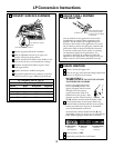
ADJUST GRILL BURNER
AIR SHUTTER
The air shutters for the grill burner may need to
be adjusted to get better flame appearance and
ignition. The air shutters for the grill burner are
located on the bottom of the grill burner. To access
the air shutters, remove the grill grate, and then the
grill burner. Slide air shutter backward or forward
to increase or decrease the size of the air opening.
Air shutters fit snugly on the grill burner, so a
screwdriver blade may be required to make this
adjustment (see illustration). The snug fit of the air
shutter assures it will remain positioned correctly.
3
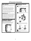
CONVERT SURFACE BURNERS
Remove all grates and burner modules.
With an adjustable wrench or an open end
wrench, remove the brass orifices.
Find the inscribed LP orifices in the holder in the
front of the electric cover beneath the cooktop.
Install the inscribed LP orifices in place of the
natural gas orifices.
Replace the burner modules and grates.
Keep all the spuds with your cooktop so you have
them if you move or get a different gas hook-up.
F
E
D
C
B
A
2
3
LP (Propane) Gas 10″ W. C . P.
Burner Output Rating in BTU/HR
Location BTUs Orifice Size Engraving
Left Rear (LR) 9,100 .0354 LP
Left Front (LF) 9,100 .0354 LP
Right Rear (RR) 9,100 .0354 LP
Right Front (RF) 9,100 .0354 LP
Turn counterclockwise to remove
Orifice
Turn clockwise to tighten
Air shutter
Insert screwdriver blade in
slot and twist with slight
pressure to allow air shutter
to slide easily
A–Yellow flames
Not normal;
check alignments
B–Yellow tips
Normal for
LP gas
C–Soft blue flames
Normal for
natural gas
LP Conversion Instructions