


12
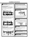
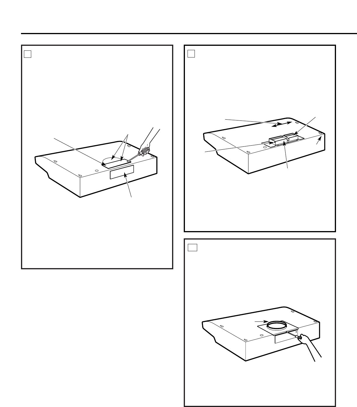
REMOVE DUCT KNOCKOUT(S)
If recirculating, non-vented ductless (optional for
JV5 Series models only), see note below and skip to
Step 11 D and proceed. We do not recommend the
recirculated configuration for JV6 Series models.
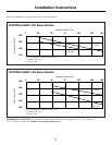
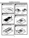
Using a flat blade screwdriver, remove the appropriate
duct knockout(s) from the top or back of the hood.
3
1
⁄4″ x 10″ Rectangular
vertical discharge.
Remove top rectangular
duct knockout only.
7″ Round vertical
discharge. Remove semi-
circular duct knockout and top
rectangular duct knockout.
3
1
⁄4″ x 10″ Rectangular
horizontal discharge. Remove
rear rectangular duct knockout only.
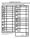
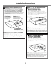
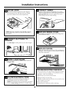
FOR 3
1
⁄4″ X 10″ RECTANGULAR
DUCTED DISCHARGE
INSTALLATIONS ONLY:
Attach exhaust adaptor/damper over knockout
opening with two exhaust adaptor screws. Make sure
damper pivot is nearest to top/back edge of hood.
Remove tape from damper flap.
Up to 1″ side-to-
side adjustment
Tape
Top/back edge
Exhaust adaptor/damper
(vertical discharge position
shown)
Pivot
FOR 7″ ROUND VERTICAL
DUCTED DISCHARGE
INSTALLATIONS ONLY:
Re-install the 7″ round exhaust adaptor with its
screws, removed in Step 2 under the “Prepare the
Hood” section.
8
9
10
7″ round
exhaust
adaptor
NOTE: The 7″ round exhaust adaptor can be installed
up to 1″ on either side of the hood center to
accommodate off-center ductwork. In extreme off-center
installations, one end of the duct connector may need
to be trimmed to clear the electrical cable clamp.
Installation Instructions
NOTE: The exhaust adaptor/damper can be installed
up to 1 inch on either side of the hood center to
accommodate off-center ductwork. In extreme off-
center installations, one end of the duct connector may
need to be trimmed to clear the electrical cable clamp.
NOTE: If the hood is to be installed in a recirculating,
non-vented ductless manner, order kit number
WB02X10707 for 30″ hood models, or kit number
WB02X10708 for 36″ hood models. These kits can
be ordered from your GE supplier. Skip to Step 11 D
and proceed.