


B
A
A
15
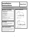
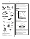
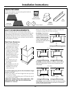
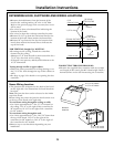
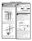
Installation Instructions
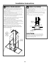
IMPORTANT: For additional support and to minimize
vibration during operation, we strongly recommend
that the hood also be secured to the back wall with
wall fasteners.
4 Alternate Mounting Method
INSTALL HOOD TO SOFFIT
OR BENEATH CABINETS
SKIP THIS STEP IF USING WALL MOUNTING
METHOD
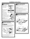
IMPORTANT: Soffit framing must be capable
of supporting 100 lbs.
When necessary, the hood may be installed so that it
is supported by the soffit.
• The soffit should be constructed with 2 x 4’s.
• Determine the installation location.
• Continue the centerline forward on the bottom of
the cabinet or soffit.
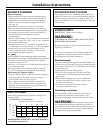
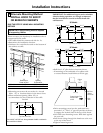
“A”“B”
Centerline to Opening
Center of Stud For Ductwork
30″ Models 14-1/2″ 10-3/4″W x 8-7/16″D
36″ Models 17-1/2″ 10-3/4″W x 8-7/16″D
• Mounting screws must be secured to 2 x 4 studs
(Dim. “A”) at locations shown in the above chart.
• Allow minimum opening (Dim. “B”) to
accommodate the duct transition in the soffit.
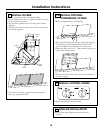
Cut a 10-3/4″ x 8-7/16″ hole through bottom of soffit or cabinet for
duct transition as shown.
• Drill four 1/8″ pilot holes in locations shown.
– If mounting to the underside of a cabinet with
a recessed bottom, install shims to fill the gap.
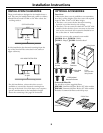
Transition
1/4" Gap
Engage Keyhole Slots
and Push Back
to Wall
Add Shims
If Bottom
Is Recessed
Back
Wall
Cabinet
or
Soffit
• Drive mounting screws into the studs until they
protrude 1/4″. This 1/4″ gap will provide clearance
to engage the keyhole slots in the top of the hood.
• Lift hood onto mounting screws. Slide back against
the rear wall.
• Pull house wiring through the knockout at the rear
or the top of the hood.
•Tighten mounting screws.
30" Models
7-1/16"
14-1/2"
C
14-1/2"
12"
29-7/8"
Top View, Front Side
2-9/16"
2-1/4"
2-3/8"
8-7/16"
10-3/4"
36" Models
7-1/16"
17-1/2"
C
17-1/2"
12"
35-7/8"
Top View, Front Side
2-9/16"
2-1/4"
2-3/8"
8-7/16"
10-3/4"
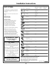
C
Top View, Front Side
2-3/8"
8-7/16"
5-3/8" 5-3/8"
Rear Wall