


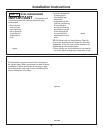
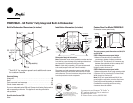
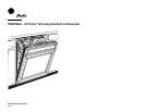
3/4" Thick Custom Panel
Template Instructions
For PDW9700J Series
The custom panel should be sized to your installation situation. See Step 1. For easier
installation the custom panel and custom handle should be attached before installing the
dishwasher. Use this template to locate mounting scr
ews and spacers on the custom panel.
IMPORTANT
• A custom handle must be installed onto the cus-
tom panel. Install the custom handle 4-1/2" max.
from the top of the panel.
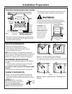
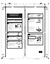
STEP 2 DRAW CENTERLINE
• Place the custom panel on a flat surface with appearance
side down.
• Locate the vertical center of the panel at the top.
• Use a carpenters square to draw a centerline from top to
bottom.
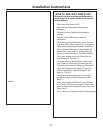
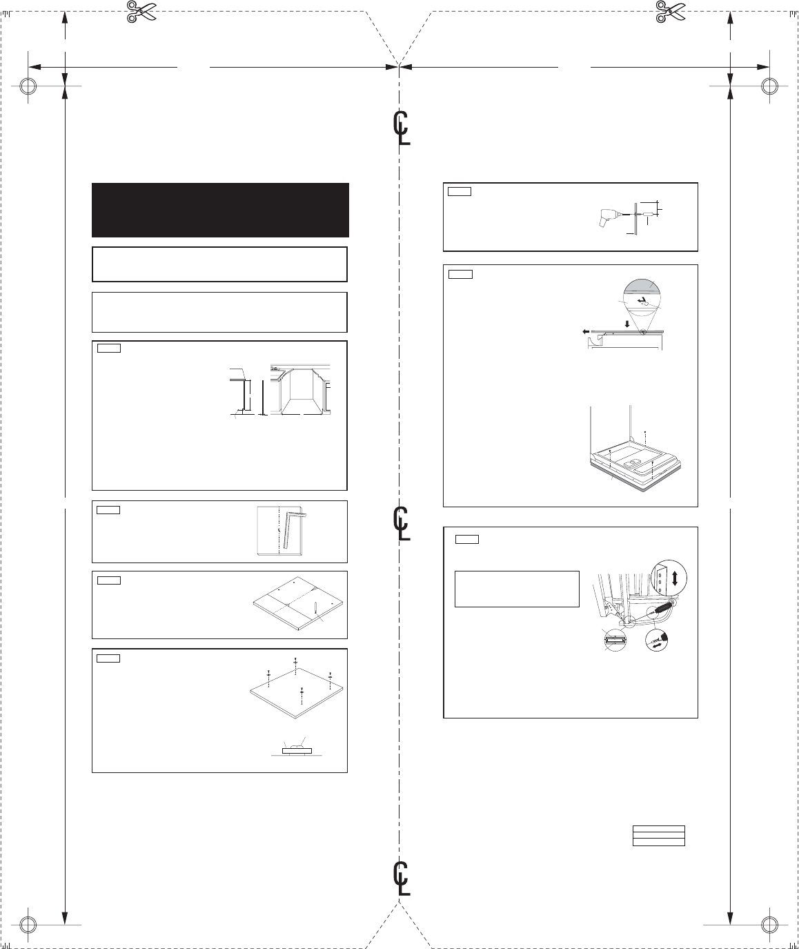
STEP 4 INSTALL MOUNTING SCREWS AND SPACERS
Mark Center
Screw Holes
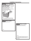
STEP 5 INSTALL CUSTOM HANDLE
A custom handle must be installed onto the
panel before the panel is secured to the dish-
washer door.
• The handle should be installed so that it aligns
with adjacent drawer handles, or 4-1/2" max.
from the top of the panel. Secure the handle in
the same manner as cabinet handles. Screws
must be countersunk into the panel.
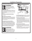
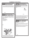
STEP 6 INSTALL ASSEMBLED PANEL
• Secure the panel to the door by inserting the
top and bottom mounting screws with spacers
into the matching keyhole slots.
• Make sure all 4 spacers engage the keyhole
slots.
• Press the panel against the door and push
downwards until the spacers are fully engaged
into the key hole slots. The panel should align
evenly with the top and sides.
• Stand the dishwasher upright.
• Open dishwasher door and drive the supplied
#8 x 1-3/4" truss head screws. Drive one screw
at the top and one on each side as shown,
through the inner door and into the custom
panel.
WARNING: Do not overtighten screws.
Excessive tightening of the screws could damage
door edges.
STEP 3 ALIGN TEMPLATE TO PANEL
• Trim template on the dotted line along all sides.
• Place the template on the panel aligned with the top edge
and the centerline. Use tape to hold in place.
• Use an awl to mark the screw hole locations indicated on
the template. Remove the template.
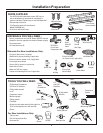
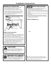
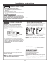
A: Determine custom panel height
1. Measure dimension A, from the underside of
the countertop to the bottom of adjacent
cabinets.
2. Subtract 1/4". This allows a 1/4" clearance
gap between the underside of the countertop
and the top of the dishwasher door.
HEIGHT = A – 1/4"
Note: 30-1/16" minimum panel height is required to cover
the door frame. Panel height varies depending on
installation. Consideration must be given to door swing
clearance above the toekick.
B: Determine custom panel width
1. Measure dimension B, the rough opening
width.
2. Subtract 1/4" for clearance (1/8" on each
side).
WIDTH = B – 1/4"
B
A
Custom
Panel Size
Floor
Cabinets
Side
View
Countertop
3/4" Max.
Bottom of
Adjacent Cabinetry
Pub. No. 31-30558
Dwg. No. 206C1559P098
N.D. 694 3/03
PARTS INCLUDED:
(4) Spacers
(4) #8 x 3/4" Hex washer head wood screws
(3) #8 x 1-3/4" Phillips truss head stainless steel
wood screws
(2) Heavy duty springs
STEP 1 DETERMINE CUSTOM PANEL SIZE
If the panel is less than 3/4" thick, shorter screws must
be used. Use #8 x 1/2" screws for 1/2" thick panels (not
supplied).
• Use a 3/32" drill bit to drill pilot holes 3/32" deep in the
marked locations.
Note: The custom panel is secured to the dishwasher door
with the spacers and screws provided. The spacer will slip
into the keyhole slots on the dishwasher door.
• Drive the supplied #8 x 3/4" hex washer head wood screws
through the spacer and into the panel.
• Install remaining spacers and screws as indicated in the
marked locations.
4-1/2" Max.
From Top
of Panel
Handle
Custom
Door Panel
Screws Must
Be Countersunk
Into Panel
Custom
Panel
Shoulder Washers
Engage Keyhole
Slots
Dishwasher
Door
Custom
Panel
Screw
Spacer
Note: The most common panel dimensions are 30-1/4" H
and 23-3/4" W.
Top of Panel Top of Panel
Trim Around Dotted Line
11-5/16"
Trim Around Dotted Line
2-9/32"
25-9/16"
11-5/16"
2-9/32"
25-9/16"
Trim Around Dotted Line
Trim Around Dotted Line
Drill 3/32"
Pilot Hole
3/32" Deep
Drill 3/32"
Pilot Hole
3/32" Deep
Drill 3/32"
Pilot Hole
3/32" Deep
Drill 3/32"
Pilot Hole
3/32" Deep
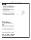
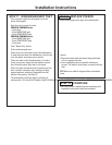
STEP 7 INSTALL DOOR SPRINGS
The dishwasher is shipped from the factory with a
temporary set of balance springs. Use the heavy
duty springs provided to balance the door after
the custom panel is installed onto the dishwasher.
The door balance system is designed to accom-
modate a wide variety of custom panels. Use the
holes on the cable to make major adjustments.
Use the holes in the leg for minor adjustments to
the door balance.
• With the dishwasher on the wood skid, close
and latch the door.
• Remove and discard both door springs.
• Attach the new heavy duty door springs. Engage
the end with the short hook into the support
leg and the long hook into the cable.
• Open and close the door.
• If the door drops open when released, increase
spring tension. If the door closes when re-
leased, decrease tension.
Note: To increase tension, move spring up one
hole. To decrease tension use lower hole. Adjust
one or both springs until door is correctly
balanced.
IMPORTANT: If the door does not open easily or
falls too quickly, check spring cable routing. The
cable is held in place by “shoulders” on the pulley.
Check to be sure the cable has not slipped over the
pulley shoulders.
Check Spring
Cable Routing
Adjust Here
to Increase or
Decrease Spring
Ten si on
Pulley
Make Minor
Spring Tension
Adjustment Here
Shoulder
INCREASE
DECREASE