


Installation Instructions
1 4
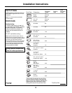
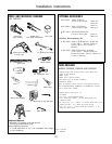
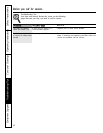
1 Ft = 0.3 m
1” = 2.5 cm
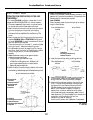
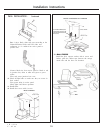
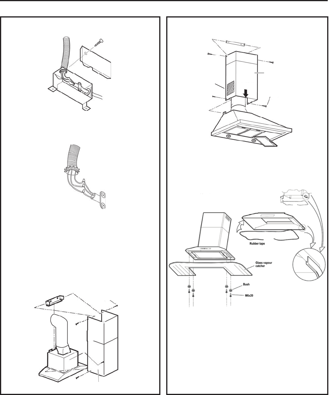
Run 3 wires; black, white and green, according to the
National Electrical Code and local codes and
ordinances, in ½" conduit from service panel to
junction box.
WALL INSTALLATION -
Continued
Connect black wire from service panel to black or red
in junction box, white to white and green to green-
yellow.
Close and secure junction box cover.
20. Check all light bulbs to make sure they are secure in
their sockets.
Turn power (On) in service panel.
Check lights and blower operation.
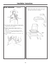
21. Install filters.
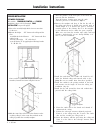
22. Install duct covers with 4 screws.
23.
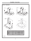
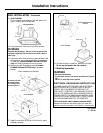
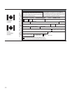
Model PVWG936:
Install the glass vapoure catcher with 4 screws and
bushes, place the rubber tape between the canopy
metal edge and the glass (see drawing)
Model PVWG936
Ø 3.5 x 9.5
Duct Cover
Models PVWS930/936 and PVWT936
Ø 3.5 x 9.5
Duct Cover
For models PVWS930/936
recirculation grids must be
mounted on the laterals of
Duct Cover.