


– 31 –
Magnetron and Magnetron TCO
WARNING: Always be certain the capacitor is
discharged before servicing. (See Capacitor and
Diode.) Mechanically discharge by placing an
insulated handle screwdriver between the diode
connection of the capacitor and the oven chassis
ground.
Note: The capacitor has an internal discharge
resistor that automatically discharges the capacitor
when the oven turns OFF. Under normal operation,
the capacitor should fully discharge within 30
seconds.
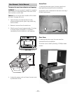
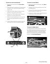
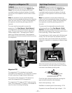
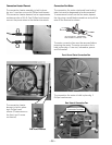
The oven must be removed to access the
magnetron. (See Oven Removal / Partial Removal.)
The magnetron is located behind the top access
cover. The top access cover is held in place by 2
Phillips-head screws. The magnetron is held in
place by 4 Phillips-head screws. The magnetron
thermostat must be disconnected before removing
the magnetron.
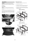
Magnetron
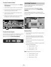
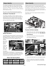
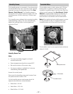
Magnetron TCO
The magnetron TCO is attached to a bracket
mounted to the magnetron. The magnetron bracket
is held in place by a single Phillips-head screw.
This position of the magnetron TCO allows it to
sense the temperature of the magnetron.
The magnetron TCO opens at 302°F and cannot be
reset. If the magnetron TCO opens, it will disable all
oven functions including the display.
Magnetron TCO
High Voltage Transformer
WARNING: Always be certain the capacitor is
discharged before servicing. (See Capacitor and
Diode.) Mechanically discharge by placing an
insulated handle screwdriver between the diode
connection of the capacitor and the oven chassis
ground.
Note: The capacitor has an internal discharge
resistor that automatically discharges the capacitor
when the oven turns OFF. Under normal operation,
the capacitor should fully discharge within 30
seconds.
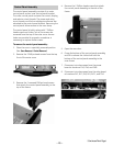
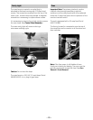
The oven must be removed to access the high
voltage transformer. (See Oven Removal / Partial
Removal.) The high voltage transformer is located
behind the top access cover. The top access cover is
held in place by 2 Phillips-head screws.
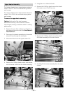
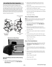
The transformer is held in place with 4 Phillips-head
screws. Two of the screws are recessed from the
top of the outer cover. Access holes are provided. A
magnetic screwdriver is necessary to capture these
screws.
Transformer
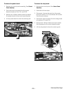
Check the high voltage transformer windings for
approximate resistance value between:
Red to white (primary) - .5 Ω
Red/Black to chassis ground (secondary) - 87 Ω
Magnetron harness (fi lament high voltage) - .2 Ω
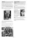
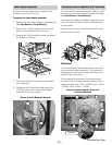
ELECTRICAL TERMINAL
RELEASE/LOCKING TAB
When disconnecting the primary and secondary
wire connections, note the wire locations. The wire
connectors use releasing locking tabs.