


– 41 –
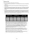
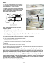
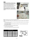
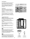
Thermistor
seulaVrotsimrehT
erutarepmeT
)C(seergeD
erutarepmeT
)F(seergeD
ecnatsiseR
smho-oliKni
02-4-k4.84 Ω
01-41k6.72 Ω
023k3.61 Ω
0105k01 Ω
Clip
9-Pin
Connector
Thermistor shown
removed from clip.
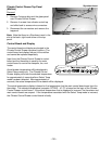
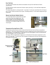
Fan Housing
Access
After removing the diffuser, the thermistor can be
accessed through the hole on the right-hand side
of the fan. After removing the thermistor from the
clip (on the inside of the fan housing), the
thermistor can be removed from the fan housing
through the hole in the top of the housing.
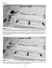
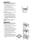
Note: When installing the diffuser onto the fan
housing, the tabs must be on the bottom and the
flat surface must be on top. Incorrect installation
will prevent the drawer from cooling and warming
properly.
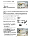
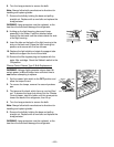
Note: All thermistors can be checked using Diagnostic Mode.
Refer to the Thermistor Values chart for resistance values. Thermistor resistance can be checked at 2
places:
• J5-5 to J5-6 at main control board. Connector J5 should be disconnected from main control board
when checking resistance.
• 9-pin connector located behind the Climate Control Drawer. Connector should be disconnected
when checking resistance.
5 VDC output to the thermistor can be checked at 2 places:
• J5-5 to J5-6 at main control board.
• 9-pin connector located behind the Climate Control Drawer.
Tabs (Down)