


– 17 –
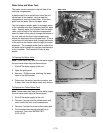
White Wire (DC Common)
The white wire is the DC common wire used for
testing. During repairs, DC polarity must be
observed. Reversing the DC polarity will cause a
shorted motor and/or board.
Red Wire (Supply)
Each motor uses an internal electronic controller
to operate the motor. Supply voltage from the
main control board remains at a constant
12 VDC.
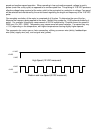
Blue Wire (Feedback/RPM)
The blue wire feeds rpm (speed) information to
the main control board, allowing the board to
maintain consistent fan speeds. Loss of feedback
from the blue wire will result in the fan accelerating
to maximum speed. Measure the fan rpm using
the frequency between the blue and white wires.
High speed - 195 to 200 Hz
Medium speed - 145 to 160 Hz
Note: Fan operates at the same speed in low and
medium.
Low speed - 145 to 160 Hz (same as medium)
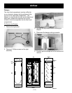
Yellow Wire (Signal)
The yellow wire is the input wire from the main
control board. The main control board provides
8.1 VDC effective voltage for low speed, 8.1 VDC
effective voltage for medium speed, and 12.6 VDC
for high speed. The fan will operate in low speed
only when the fresh food thermistor is satisfied.
Note: When testing these motors:
• You cannot test with an ohmmeter.
• DC common is not AC common.
• Verify 2 voltage potentials:
a. Red to white - power for internal controller.
b. Yellow to white - power for fan.
• Observe circuit polarity.
• Motors can be run for short periods using a
9-volt battery. Connect the white wire to the
negative (-) battery terminal only. Connect the
red and yellow wires to the positive (+) battery
terminal.
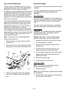
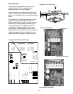
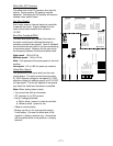
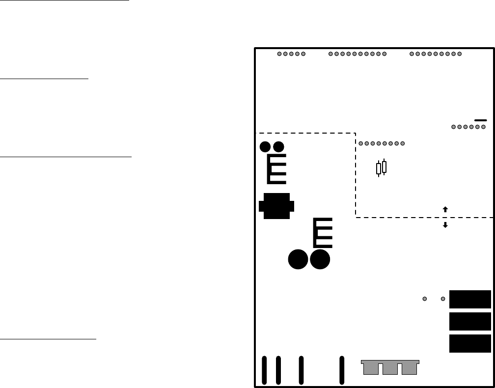
GEA01196
Pin 1 J8
Compressor
Pin 1 J9
Defrost Heater
Pin 1 J11
Line
Evaporator Fan Tach.
J2 Pin 1
Personality Input 5
Pin 2
Fan Common
Pin 3
Evaporator Fan
Pin 4
Condenser Fan
Pin 5
FF Fan
Pin 6
QuickChill Damper1 +
J5 Pin 1
QuickChill Damper1 -
Pin 2
QuickChill Damper2 +
Pin 3
QuickChill Damper2 -
Pin 4
+5V
Pin 5
QuickChill Thermistor
Pin 6
QuickChill Fan
Pin 7
Fan +12V
Pin 8
FF1 Thermistor
J1 Pin 1
FF2 Thermistor
Pin 2
FZ Thermistor
Pin 3
Evaporator Thermistor
Pin 4
+5V
Pin 5
Personality Input 1
Pin 6
Personality Input 2
Pin 7
Personality Input 3
Pin 8
Personality Input 4
Pin 9
Damper - Blue
J3 Pin 1
Damper - White
Pin 2
Damper - Red
Pin 3
Damper - Yellow
Pin 4
FF Encoder Select
Pin 5
Comm. Tx/Rx
J4 Pin 1
Comm. +12V
Pin 2
Comm. Common
Pin 3
Discrete Disp. Input 1
Pin 4
Discrete Disp. Input 2
Pin 5
FZ Encoder Select
Pin 6
Encoder Signal
Pin 7
Encoder Signal
Pin 8
Encoder Signal
Pin 9
Encoder Signal
Pin 10
Pin 1 J12
Monogram Drain Pan Heater
Pin 9 J7
Neutral
Pin 8
NIC
Pin 7
FZ Door Switch
Pin 6
FF Door Switch
Pin 5
QuickChill Heater
Pin 4
Auger Motor Interlock
Pin 3
Water Valve
Pin 2
Crusher Solenoid
Pin 1
Auger Motor
Pin 1
QuickChill Htr.
Pin 2
QuickChill Htr.
Low Voltage DC
120 VAC