


12
D.
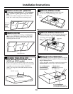
Recirculating (non-vented ductless–
JN327 and RN328, and optional on
JV347 and JV367 models only)
• Use the hood as a template and mark the locations
on the cabinet for the electrical wiring and keyhole
screw slots.
• Since the hood is to be recirculated (not to be vented
outside), do not cut out any vent openings in the wall
or cabinet bottom.
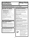
Installation Instructions
Wood shims
(recessed-bottom cabinets only–shims must be a
minimum of 3/8″ thick and cut to fit the width
of the inner recessed cabinet bottom)
Cabinet front
Center line
Electrical access hole
(in wall)
Hood mounting screws (4)
Horizontal duct
access hole
Cabinet
bottom
13
3
⁄4″ (30″ hood)
16
3
⁄4″ (36″ hood)
1
1
⁄4″
1
⁄2″
3
3
⁄4″
5
1
⁄4″
5
1
⁄4″
7
3
⁄4″
13
3
⁄4″ (30″ hood)
16
3
⁄4″ (36″ hood)
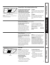
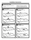
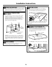
C.
Outside rear exhaust
(Horizontal duct–3
1
⁄4
″
x 10
″
Rectangular)
• Use the diagram or the hood as a template and
mark the locations on the cabinet for ductwork,
electrical wiring and keyhole screw slots.
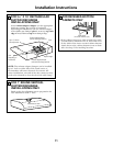
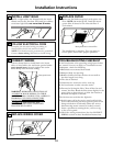
RUN WIRES
Run the electrical wires through the wall or
cabinet according to National Electrical Code
and applicable local codes.
NOTE: DO NOT turn the power on until
installation is complete.
13
CUT HOLES
Cut holes at marked locations for duct and electrical
wiring. For the vertical duct, cut out 3/4″ extra
toward the front of the cabinet so you can move the
duct freely when installing the hood. It may also ease
installation by cutting the hole 10
1
⁄2″ instead of 10″.
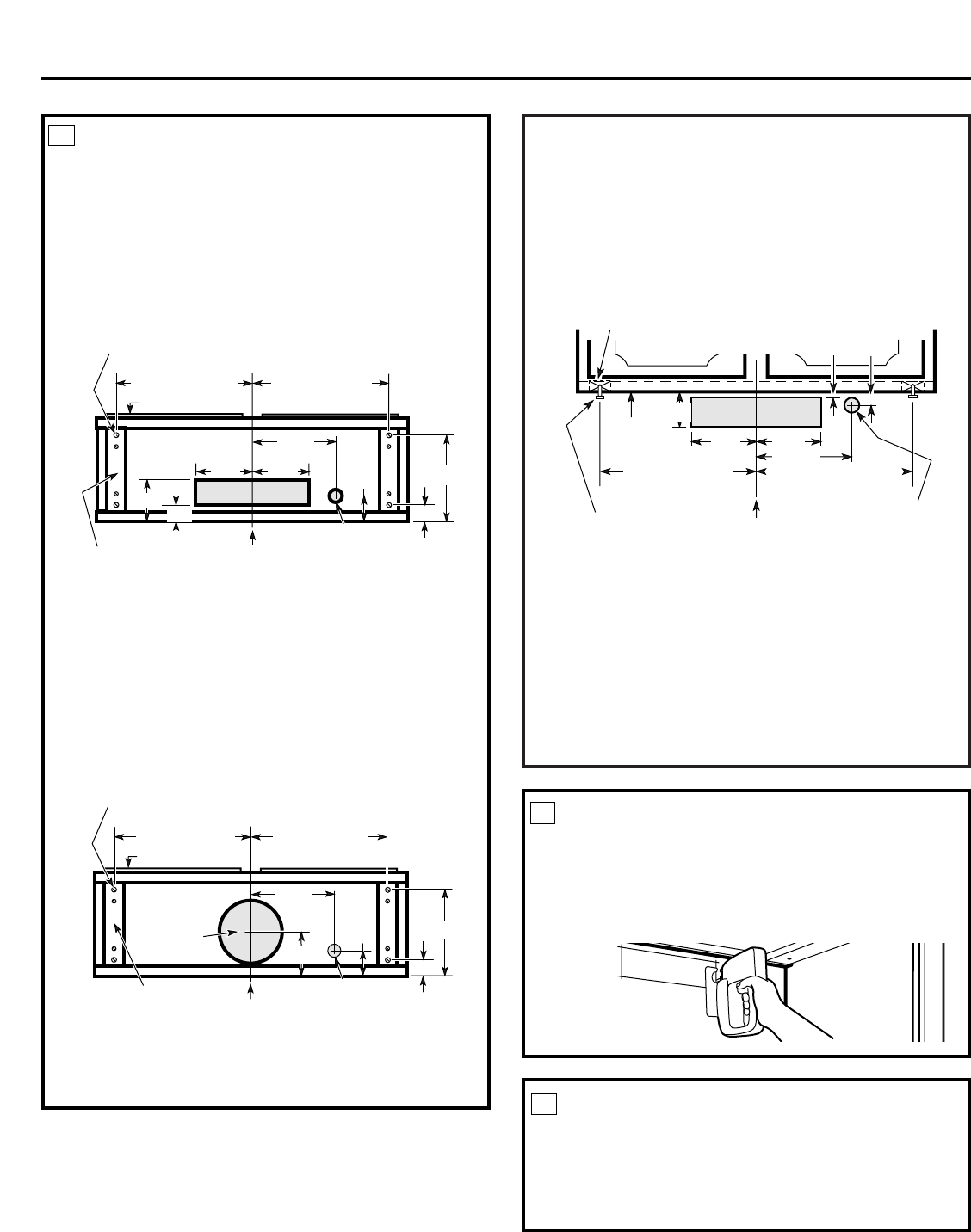
12
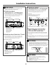
MARK HOLES
Select the vent option that your installation will
require and proceed to that section:
Hood mounting screws (4)
13
3
⁄4″ (30″ hood)
16
3
⁄4″ (36″ hood)
13
3
⁄4
″
(30
″
hood)
16
3
⁄4
″
(36
″
hood)
Cabinet front
Center
line
Electrical access hole
(in cabinet bottom)
Wood shims
(recessed-bottom cabinets
only–shims must be a
minimum of 3/8″ thick
and cut to fit the width
of the inner recessed
cabinet bottom)
Vertical duct
access hole
9
5
⁄8″
1
3
⁄8″
1
1
⁄4″
7
3
⁄4″
3
3
⁄4″
1
⁄2″
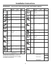
A.
Outside top exhaust
(Vertical duct–3
1
⁄4
″
x 10
″
Rectangular)
• Use the diagram or the hood as a template and
mark the locations on the cabinet for ductwork,
electrical wiring and keyhole screw slots.
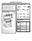
B.Outside
top exhaust (Vertical duct–7″ Round)
• Use the diagram or the hood as a template and
mark the locations on the cabinet for ductwork,
electrical wiring and keyhole screw slots.
Hood mounting screws (4)
13
3
⁄4″ (30″ hood)
16
3
⁄4″ (36″ hood)
13
3
⁄4
″
(30
″
hood)
16
3
⁄4
″
(36
″
hood
)
Cabinet front
Center
line
Electrical access
hole (in cabinet bottom)
Wood shims
(recessed-bottom cabinets
only–shims must be a minimum
of 3/8″ thick and cut to fit the
width of the inner recessed
cabinet bottom)
Access
hole for 7″
round duct
9
5
⁄8″
1
3
⁄8″
1
1
⁄4″
7
3
⁄4″
5
3
⁄4″
Cabinet
bottom
8″ DIA.
HOLE
Cabinet Bottom
11
5
1
⁄4″
5
1
⁄4″