


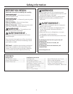
Design Guide
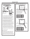
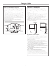
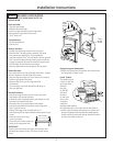
THE INSTALLATION SPACE
*For a standard installation of Custom-Framed unit: The
product must be installed so that the front face will project 2"
forward of adjacent cabinets. This position will allow a full door
swing and prevent interference with adjacent cabinetry. The
opening between cabinets must be 23-3/4" minimum.
*For a standard installation of Stainless Steel unit: The product
must be installed so that the front face will project 1-3/4"
forward of adjacent cabinets. This position will allow a full door
swing and prevent interference with adjacent cabinetry. The
opening between cabinets must be 23-3/4" minimum.
**For a flush installation of Stainless Steel unit: Install a
1/2"-wide ller strip on the hinge side. The ller strip will act as
a spacer between the door case and adjacent cabinets and will
prevent interference with the cabinet door swing. Recess the
ller strip 2" back from the front face of the unit, or even with
the front edge of the product case (behind the gasket). The width
of the opening must be 24-1/4" (including the 1/2" ller strip).
*** For a flush installation of Custom-Framed unit: Install a
1"-wide ller strip on the hinge side. The ller strip will act as
a spacer between the door case and adjacent cabinets and
will prevent interference with the cabinet door swing. Recess
the ller strip 2" back from the front face of the unit, or even with
the front edge of the product case (behind the gasket). The width
of the opening must be 24-3/4" (including the 1" ller strip).
• The wine chiller, wine reserve and beverage center can
be installed freestanding.
Additional Specifications
• A 120 volt 60Hz., 15 or 20 amp power supply is required.
An individual properly grounded branch circuit or circuit
breaker is recommended. Install a properly grounded
3-prong electrical receptacle recessed into the back wall
as shown. Electrical must be located on rear wall as shown.
NOTE: GFI (ground fault interrupter) is not recommended.
3
NOTE:
Handle and handle
standoff depth is 1-3/4"
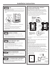
THE INSTALLATION SPACE (cont.)
These products will t ush to
adjacent cabinets when installed
with a Dim. A-width ller panel
or cleat. The ller panel should
be recessed or set back behind
the door and even with the front
edge of the product case.
Product Dim. A
ZDWI240, ZDBI240 1"
ZDWC240, ZDWR240 1/2"
ZDBC240, ZDBR240 1/2"
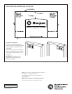
In a standard installation,
the product will project forward
of adjacent cabinets. See Dim. A.
Flush
Installation
CABINET
CABINET
CABINET
CABINET
Dim. A
Dim. A
120°
120°
110°
110°
Filler panel or cleat
to be set back even
with front of case.
Front edge of product case
Front face
Front face
Front edge of product case
Standard
Installation
Product Dim. A
ZDWI240, ZDBI240 2"
ZDWC240, ZDWR240 1-3/4"
ZDBC240, ZDBR240 1-3/4"