


46
Chapter 6: Maintaining Your Filtered Enclosure
Setting the Inflow Face Velocity
with the Speed Control
Adjustment
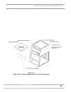
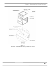
1. Remove the front panel by loosening the (2) Phillips screws
on top that secure the front panel.
2. The speed control is located on the electrical subassembly
located behind the switched control panel and below the
front panel. See Figure 6-1.
3. Adjust the speed control with a small Phillips screwdriver
by turning the screw counterclockwise to increase blower
speed or clockwise to decrease the blower speed. The
speed control is very sensitive, so proceed with caution.
4. Measure the inflow velocity per the averaging technique
outlined in Chapter 3 and adjust the speed control slowly
for the desired speed. Allow the speed to stabilize and re-
measure the inflow velocity to confirm.
5. Replace the front panel and tighten the screws.
Calibrate and Operate the Airflow
Monitor
Guardian Airflow Monitor (LED Monitor)
Refer to Figure 6-2 for operation and calibration.
Labconco Airflow Monitor / Airflow Switch Operation
The Guardian Airflow Monitor (LED) consists of a circuit board
and an airflow switch. This switch indicates airflow as safe or low.
It does not provide an actual face velocity, but a small setscrew in
the back of the sensor can adjust the airflow level that it classifies
as “good/safe” or “low/alert.”
The circuit board provides power to the sensor and also contains a
“safe (green)” and “alert (red)” airflow LED indicators, as well as
a “SILENCE ALARM” button to quiet the audio alarm. When
first powered up, the PCB will light both red and green LED
indicators and sound the alarm to indicate it is working. After 5
seconds, the air monitor will indicate either good or bad airflow
based on what the connected airflow switch detects. For low
airflow, the unit will wait for 10 seconds of bad indications before
it sounds both the audio alarm and the red “alert” LED indicator. If
Options