


47
Chapter 6: Maintaining Your Filtered Enclosure
the “SILENCE ALARM” button is pressed, the audio alarm will
be silenced, but the red “alert” LED will remain on. The alarm is
silenced indefinitely unless an airflow change is detected. If safe
airflow is later detected for 10 seconds, the green “safe” LED will
be lit and the “alert” (red) LED will be shut off. At any time the
airflow is safe/good, one can press the SILENCE ALARM test
button and the audio alarm and the red LED will turn on as long as
this button is held down. The PCB has also a two-pin connector
for use as an external output with isolated relay contacts that close
when the red/alert LED is lit (low airflow). These relay contacts
are not affected by the “SILENCE ALARM” button.
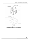
The PCB is mounted behind the front panel using standoffs and an
appropriate label is used to highlight the “SILENCE ALARM”
button with clear areas for the red and green LED’s. No holes to
allow sound to be broadcast louder are necessary.
The PCB can be prepared as a factory special with an additional
connector for the following external inputs, and having the
following possible functions:
• External Alarm allows an external signal to sound the alarm,
such as a sash open switch, or a “fail” signal from the building
airflow system.
• Alarm Disable allows an external signal to prevent a “low”
airflow alarm from occurring.
• Night Setback allows an external signal to prevent a “low”
airflow alarm from occurring (not any different from Alarm
Disable above other than the terminology.)
• Contact Labconco for ordering information on this special
PCB.
Calibration
1. Ensure the flow switch and alarm circuit board are installed
and operational.
2. Allow the enclosure to operate for at least two minutes.
3. If factory installed, the monitor will alarm at 60±10 fpm
with the inflow velocity set at 90±10 fpm.
4. To change the factory setting, set the inflow velocity
required by your Safety Officer to the desired alarm
condition using the speed control adjustment procedure
outlined in Chapter 6.
Once the alarm condition is set, use a small screwdriver to turn the
adjustment screw on the airflow switch counterclockwise (facing
the screw) until the “low” airflow red LED lights and the audible
flow alarm sounds.