SERVICING
36
4. Check the continuity of the thermostat and wiring. Repair
or replace as necessary.
Resistance Heaters
1. Set room thermostat to a higher setting than room
temperature so both stages call for heat.
2. With voltmeter, check for 24 volts at each heater relay.
Note: BBA/BBC heater relays are DC voltage.
3. No voltage indicates the trouble is in the thermostat or
wiring.
4. Check the continuity of the thermostat and wiring. Repair
or replace as necessary.
NOTE: Consideration must be given to how the heaters are
wired (O.D.T. and etc.). Also safety devices must be checked
for continuity.
S-3B COOLING ANTICIPATOR
The cooling anticipator is a small heater (resistor) in the
thermostat. During the "off" cycle, it heats the bimetal
element helping the thermostat call for the next cooling cycle.
This prevents the room temperature from rising too high
before the system is restarted. A properly sized anticipator
should maintain room temperature within 1 1/2 to 2 degree
range.
The anticipator is supplied in the thermostat and is not to be
replaced. If the anticipator should fail for any reason, the
thermostat must be changed.
S-3C HEATING ANTICIPATOR
The heating anticipator is a wire wound adjustable heater
which is energized during the "ON" cycle to help prevent
overheating of the conditioned space.
The anticipator is a part of the thermostat and if it should fail
for any reason, the thermostat must be replaced. See the
following tables for recommended heater anticipator setting
in accordance to the number of electric heaters installed.
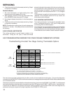
S-3D TROUBLESHOOTING ENCODED TWO STAGE COOLING THERMOSTATS OPTIONS
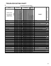
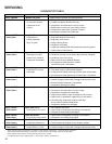
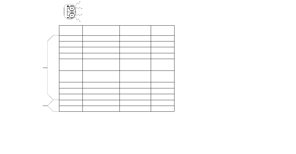
Troubleshooting Encoded Two Stage Cooling Thermostats Options
TEST FUNCTION SIGNAL OUT SIGNAL FAN
S
T
E
T
S1 +
* S1 - *
S1 + -
S2 +
S2 -
S2 + -
S3 +
* S3 - *
* S3 + - *
R + -
COM
LOW SPEED COOL
* LO SPEED COOL *
HI SPEED COOL
LO SPEED HEAT
O
LO SPEED HEAT
HI SPEED HEAT
G
N/A
N/A
24 VAC
GND
YCON +
* YCON - *
YCON + -
W1 HEATER
ED -
( FUTURE USE )
W1 HEATER
W2 HEATER
NONE
N/A
N/A
R TO T'STAT
COM TO T'STAT
Y1
* Y / Y2 HI *
Y / Y2
W / W1
O
W / W1
EM / W2
G
N/A
N/A
R
C1 , C2
* ERROR CONDITION ( DIODE ON THERMOSTAT BACKWARDS )
* ERROR CONDITION ( S3 CAN ONLY READ + )
INDICATION
* ERROR CONDITION ( S3 CAN ONLY READ + )
INPUT
FROM
THERMOSTAT
POWER
TO
THERMOSTAT
NOTES:
1.) THE TEST SPADE CAN BE CONNECTED TO ANY OTHER TEST SPADE ON EITHER BOARD.
2.) THE + LED WILL BE RED AND WILL LIGHT TO INDICATE + HALF CYCLES.
THE - LED WILL BE GREEN AND WILL LIGHT TO INDICATE - HALF CYCLES.
BOTH RED AND GREEN ILLUMINATED WILL INDICATE FULL CYCLES DENOTED BY + - .
3.) SIGNAL OUT CONDITION FOR W1 , W2 HEATER WILL BE AFFECTED BY OT1 PJ4 AND OT2 PJ2
JUMPERS AND OUTDOOR THERMOSTATS ATTACHED. THE TABLE ABOVE ASSUMES OT1 PJ4 IS
REMOVED AND OT2 PJ2 IS MADE WITH NO OUTDOOR THERMOSTATS ATTACHED.
SEE NOTE 3
SEE NOTE 3
The chart above provides troubleshooting for either version of the encoded thermostat option. This provides diagnostic
information for the GMC CHET18-60 or a conventional two cool / two stage heat thermostat with IN4005 diodes added as called
out in the above section.
A test lead or jumper wire can be added from the test terminal to any terminal on the B13682-74 or B13682-71 variable speed
terminal board and provide information through the use of the LED lights on the B13682-71 VSTB control. Using this chart,
a technician can determine if the proper input signal is being received by the encoded VSTB control and diagnose any
problems that may be relayed to the output response of the B13682-74 VSTM control.


