


SERVICING
51
3. Connect good capacitors of the right MFD and voltage
rating into the circuit as shown.
4. With power ON, close the switch.
WARNING
Line Voltage now present.
A. If the compressor starts and continues to run, the cause
for failure is somewhere else in the system.
B. If the compressor fails to start - replace.
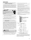
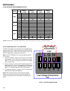
COPELAND COMPRESSOR
03 A 12345 L
Y
EAR
MONTH
SERIAL
NUMBER
PLANT
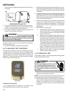
S-18 TESTING CRANKCASE HEATER
(OPTIONAL ITEM)
The crankcase heater must be energized a minimum of four
(4) hours before the condensing unit is operated.
Crankcase heaters are used to prevent migration or accumu-
lation of refrigerant in the compressor crankcase during the
off cycles and prevents liquid slugging or oil pumping on start
up.
A crankcase heater will not prevent compressor damage
due to a floodback or over charge condition.
WARNING
Disconnect ALL power before servicing.
1. Disconnect the heater lead in wires.
2. Using an ohmmeter, check heater continuity - should
test continuous. If not, replace.
NOTE: The positive temperature coefficient crankcase heater
is a 40 watt 265 voltage heater. The cool resistance of the
heater will be approximately 1800 ohms. The resistance will
become greater as the temperature of the compressor shell
increases.
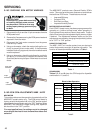
S-21 CHECKING REVERSING VALVE AND
SOLENOID
Occasionally the reversing valve may stick in the heating or
cooling position or in the mid-position.
When stuck in the mid-position, part of the discharge gas
from the compressor is directed back to the suction side,
resulting in excessively high suction pressure. An increase
in the suction line temperature through the reversing valve
can also be measured. Check operation of the valve by
starting the system and switching the operation from COOL-
ING to HEATING cycle.
If the valve fails to change its position, test the voltage (24V)
at the valve coil terminals, while the system is on the
COOLING cycle.
If no voltage is registered at the coil terminals, check the
operation of the thermostat and the continuity of the con-
necting wiring from the "O" terminal of the thermostat to the
unit.
If voltage is registered at the coil, tap the valve body lightly
while switching the system from HEATING to COOLING,
etc. If this fails to cause the valve to switch positions, remove
the coil connector cap and test the continuity of the reversing
valve solenoid coil. If the coil does not test continuous -
replace it.
If the coil test continuous and 24 volts is present at the coil
terminals, the valve is inoperative - replace it.
S-24 TESTING DEFROST CONTROL
To check the defrost control for proper sequencing, proceed
as follows: With power ON; unit not running.
1. Jumper defrost thermostat by placing a jumper wire
across the terminals "DFT" and "R" at defrost control
board.
2. Connect jumper across test pins on defrost control
board.
3. Set thermostat to call for heating. System should go into
defrost within 21 seconds.
4. Immediately remove jumper from test pins.
5. Using VOM check for voltage across terminals "C & O".
Meter should read 24 volts.
6. Using VOM check for voltage across fan terminals DF1
and DF2 on the board. You should read line voltage (208-
230 VAC) indicating the relay is open in the defrost
mode.
7. Using VOM check for voltage across "W2 & C" terminals
on the board. You should read 24 volts.
8. If not as above, replace control board.
9. Set thermostat to off position and disconnect power
before removing any jumpers or wires.
NOTE: Remove jumper across defrost thermostat before
returning system to service.
S-25 TESTING DEFROST THERMOSTAT
1. Install a thermocouple type temperature test lead on the
tube adjacent to the defrost control. Insulate the lead
point of contact.
2. Check the temperature at which the control closes its
contacts by lowering the temperature of the control. Part
# 0130M00009P which is used on 2 and 2.5 ton units
should close at 34°F ± 5°F. Part # 0130M00001P which
is used on 3 thru 5 ton units should close at 31°F ± 3°F.