Installation
8 312786G
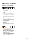
15X247 Auto Dump Valve Kit
1. Close the component A and component B shutoff
valves on the fluid manifold.
2. Trigger the gun to relieve fluid pressure downstream
of the fluid manifold.
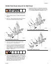
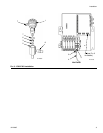
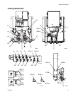
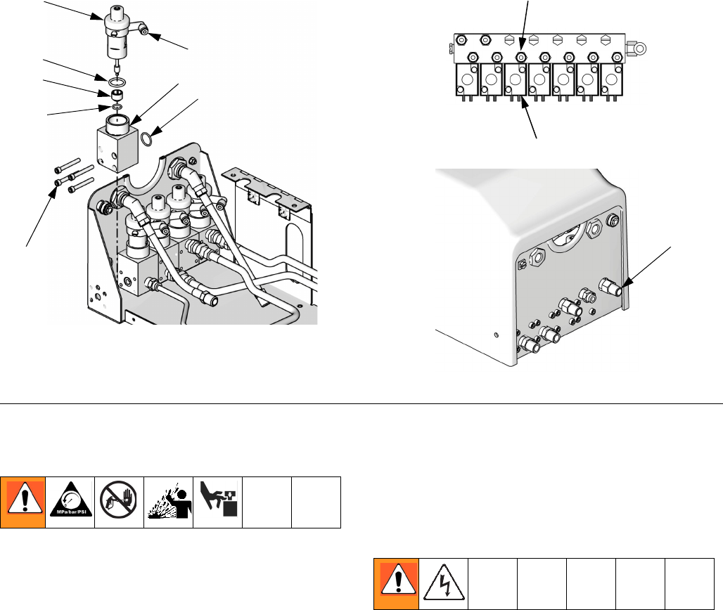
3. See F
IG
. 9. Install the small o-ring (3), seat retainer
(6), large o-ring (7), and dump valve (1) in the valve
adapter (2).
4. Install the valve adapter (2) in the mixed material
line, downstream of the static mixer and as close to
the gun as possible.
NOTE: Connect the static mixer to one 1/4 npt port of
the valve adapter.
5. Install the nipple (8) in the other port of the adapter
(2). Connect the gun line to this nipple.
6. Connect a 1/4 npsm(f) dump hose (not supplied) to
the 1/4 npsm(m) threaded stud at the bottom of the
adapter (2). When the gun closes, the dump valve
opens and fluid is dumped through the stud.
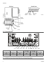
7. Shut off all power to the fluid panel. Open the fluid
panel. See the Wall Panel detail in F
IG
. 9. Install the
solenoid (5) at the correct position (GFB1 or GFB2)
on the solenoid manifold. Connect the solenoid
wires to J8 on the fluid panel control board as
shown in F
IG
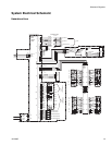
. 3. Also see the System Electrical
Schematic on page 13.
8. Install the tube connector (9) in the solenoid mani-
fold. Connect the tubing (4) between the connector
and the tube fitting (T) on the dump valve (1). See
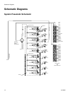
System Pneumatic Schematic, page 10.
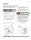
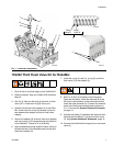
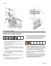
F
IG
. 8: 15V202 Kit Installation
TI12655a
TI13047a
TI13046a
5
6
1
10
3
2
4
8
9
6
T


