


4
Model TCF and Models QEI/QEID Centrifugal
®
Centrifugal AirfoilMixed Flow
DANGER
High voltage electrical input is needed for this
equipment. This work should be performed by a
qualified electrician.
WARNING
Disconnect and secure to the “Off” position all
electrical power to the fan prior to inspection
or servicing. Failure to comply with this safety
precaution could result in serious injury or death.
Fan Duct
Flexible Sleeve
Fan Duct
Companion Flange
Flexible Sleeve
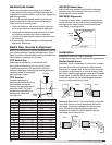
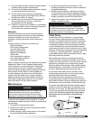
1 Fan
Wheel
Dia.
Good
Poor
Turning
Vanes
1 Fan
Wheel
Dia.
Length of
Straight Duct
Poor
Good
1 Fan
Wheel
Dia.
Good
Poor
Turning
Vanes
1 Fan
Wheel
Dia.
Length of
Straight Duct
Poor
Good
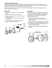
Non-Ducted Installation
Inlet Clearance – Installation of a fan with an open
inlet too close to a wall or bulkhead will cause
reduced fan performance.
It is desirable to have a
minimum of one fan wheel
diameter between the fan
inlet and the wall.
Free Discharge – Free
or abrupt discharge
into a plenum results
in a reduction in fan
performance. The effect
of discharge static regain
is not realized, and
performance is reduced.
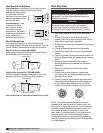
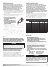
Duct Connections
It is highly recommended to use a flexible sleeve
connection instead of a rigid duct connection. This will
reduce vibration transmission through the ductwork.
Slip-Fit End Connection (QEI/QEID)
Directly attach the flexible sleeve to the duct and fan.
No additional parts are required.
Fan Duct
Flexible Sleeve
Fan Duct
Companion Flange
Flexible Sleeve
Flanged End Connection (TCF/QEI/QEID)
Optional companion flanges are bolted to the fan to
provide a slip-fit connection for a flexible sleeve.
Note: Flexible sleeve & attachment hardware not provided.
Unit Start-Up
1. Disconnect and lock-out all power switches to
fan.
2. Check all fasteners, set screws and locking
collars on the fan, wheel, bearings, drive, motor
base and accessories for tightness.
3. Rotate the fan wheel by hand and assure no parts
are rubbing.
4. Check for bearing alignment and lubrication.
5. Check the V-belt drive for proper alignment and
tension.
6. Check all guarding (if supplied) to ensure that it is
securely attached and not interfering with rotating
parts.
7. Check operation of variable inlet vanes or
discharge dampers (if supplied) for freedom of
movement.
8. Check all electrical connections for proper
attachment.
9. Check housing and ductwork, if accessible,
for obstructions and foreign material that may
damage the fan wheel.
10. Check for proper wheel rotation by momentarily
energizing the fan. Rotation should correspond
to the rotation decal affixed to the unit (CCW
rotation is correct as viewed from the fan inlet).
NOTE: One of the most frequently encountered
problems with centrifugal fans is motors which are
wired to run in the wrong direction. This is especially
true with 3-phase installations where the motor will
run in either direction, depending on how it has
been wired. To reverse rotation of a 3-phase motor,
interchange any two of the three electrical leads.
Single phase motors can be reversed by changing
internal connections as described on the motor label
or wiring diagram.