


Connection and Operation of Temperature
Response Devices (RRL standard, OCI option,
and PRV option)
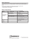
RRL - Dampers will be supplied with a thermostat-type
temperature response device, as a standard. The device is a RRL
(resettable link device), which only incorporates one thermostat
and therefore the damper remains closed as soon as its sensor
temperature is reached. The RRL does not contain blade
indication switches. Refer to Figure 5 for wiring of the RRL
thermostat.
If RRL is ordered with a pneumatic actuator, an EP switch is
required with an appropriate electric power circuit to allow the
electric thermostat to control the pneumatic actuator.
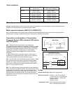
OCI - The OCI (open or closed indicator) option contains a single
pole, double throw switch used to indicate the damper blade
position. The switch provides a positive open or closed signal
when used in conjunction with remote indicator lights. Refer to
Fig. 7 for wiring of the OCI option.
PRV - The PRV (pneumatic relief valve) option is heat responsive
device used with pneumatic actuators. This can be used in place
of EP switch where a RRL is used. The PRV activates when
temperature in excess of the temperature of the fusible link are
detected. When the fusible link melts, air from the actuator is
exhausted to close the dampers. Pneumatic actuators are to be
piped per local code.
RATINGS
Integral Switch Type: Single Pole, double throw
Electrical Capacity: 10 Amps,
1
/3 hp, 120 or 240 Vac
1
/2 Amp, 125 Vdc;
1
/4 Amp 250 Vdc
5 Amps, 120 Vac “L” (lamp load)
1.0 Amps, 24 Vac
1.5 Amps, 24 Vdc
Temperature Limit: 165° F (standard primary sensor)
212° F (optional primary sensor)
L1
DAMPER
INDICATOR
LIGHTS
L2
CLOSED POSITION OF THE DAMPER.
A BLUE MARKER INDICATE THE
THE SWITCH WIRES WRAPPED WITH
NOTE:
YELLOW
ELECTRICAL CAPACITY = 10AMP @ 120 / 240 VAC
YELLOW
YELLOW
YELLOW
NO
NO
S2
S1
BY OTHERS
OCI Wiring
Fig. 5
Fig. 6
L1
M
L2
ELECTRIC DAMPER
ACTUATOR OR PNEUMATIC
SOLENOID VALVE
PRIMARY TEMP
SENSOR
ELECTRICAL CAPACITY = 10 AMP @ 120 / 240
VA
C
BLACK
ORANGE
P
NC
BLACK
WHITE/RED
RRL Wiring
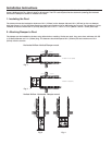
Damper model Maximum Single Maximum Overall size for
Section size Multi-section dampers
IMO-310 32 in. x 32 in. 64 in. x 32 in.
(813mm x 813mm) (1626mm x 813mm)
SSIMO-310 32 in. x 32 in. 64 in. x 32 in.
(813mm x 813mm) (1626mm x 813mm)
IMO-311 32 in. x 32 in. 64 in. x 32 in.
(813mm x 813mm) (1626mm x 813mm)
SSIMO-311 32 in. x 32 in. 64 in. x 32 in.
(813mm x 813mm) (1626mm x 813mm)
Size Limitations
Manually operated dampers (IMO-310 & SSIMO-310)
Manually operated dampers utilize a spring and fusible link assembly to close the damper during elevated temperature
conditions. No electrical power is required for these models.
Motor operated dampers (IMO-311 & SSIMO-311)
Motor operated dampers are supplied with an electric thermal response device which cuts power to the spring return
actuator upon sensing an elevated temperatures. See below for electrical connections.