


5
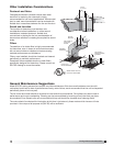
Ceiling Exhaust and Inline Fans
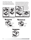
Wire the Fan
115 & 277 Volt
Black wire is “Hot”
White wire is “Neutral”
Green wire is “Ground”
220 - 240 Volt
Black wire is “Hot”
White wire is “Hot”
Green wire is “Neutral/Ground”
Fig. 7a Fig. 7b
1. Remove wiring cover.
If fan/light combination
is being used, make
sure the fan plug is
connected to the fan
receptacle and the light
plug is connected to
the light receptacle,
shown in Fig. 6.
Using proper wire
connectors, wire the fan as shown in Fig. 7a.
For wiring of light proceed to Fig. 7b.
2. Push all wiring into the unit’s cover and replace
wiring cover.
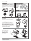
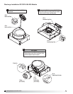
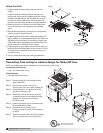
For Frame Construction:
Position unit between
joists. Position brackets
such that bottom
edge of housing will
be flush with finished
ceiling, and tighten the
adjustable mounting
brackets, shown in
Fig. 3.
For Hanging
Installations:
Use Greenheck’s
optional vibration
isolator kit Part Number
VI Kit. Using the fan’s
standard adjustable
mounting brackets and
10 by 32 threaded rod
(by others), hang unit as
shown in Fig. 4.
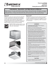
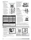
Install the Fan
1. For best
performance,
choose a location
with the shortest
possible duct run
and minimum
number of elbows.
Do not mount near
cooking equipment, as
shown in Fig. 1.
2. Attach adjustable
mounting brackets
to fan, but leave the
screws loose until
proper height is
determined, shown
in Fig. 2. Cut hole to
dimensions shown
in table below:
3. Installation of ductwork
is critical to the performance
of the fan, shown in Fig. 5.
Straight ductwork (1) or
ductwork that turns in
the same direction as the
wheel (2) is recommended.
Ductwork turning opposite
the wheel direction (3) will
cause turbulence and back
pressure resulting in poor
performance.
4. Slide ductwork over the fan’s discharge collar and
securely attach it with sheet metal screws.
Make sure the screws do not interfere with damper
operation. Check damper to make sure it opens freely.
Top Mount
Bottom Mount
Brackets can be
used in either
position to adapt to
most mounting
situations
Bottom Mount
Fig. 2
Slots in the
brackets
allow fine
adjustment
for flush
fit with
wall/ceiling
opening
AIRFLOW
1
(GOOD)
3
(POOR)
2
(GOOD)
Fig. 5
45° 45°
Do not install
fan in this area
Ceiling Openings
Sizes Fan or Fan/Light Fan/CRD
SP-A50, A70, A90
SP-A110, A125, A190
10
7
⁄8
x 13
3
⁄8
11
1
⁄8
x 13
7
⁄16
SP-A200, A250, A290, A390 12
1
⁄8
x 14
1
⁄4
12
1
⁄4
x 14
3
⁄8
SP-A700 23
3
⁄4
x 11
3
⁄4
24
1
⁄8
x 12
1
⁄4
SP-A410, A510, A710, A780 14
3
⁄4
x 18
3
⁄8
14
7
⁄8
x 18
7
⁄16
SP-A900, A1050, A1410,
A1550
14
3
⁄4
x 24 14
7
⁄8
x 24
1
⁄8
SP-B 50 - 200 14
1
⁄8
x 11
3
⁄4
14
3
⁄8
x 12
1
⁄4
Fig. 3
Fig. 4
NOTE
Model SP-A 50-90 are standard with a round duct.
Should Model SP-A 110-190 require a round duct,
Model RDC (Round Duct Connector) may be ordered
from Greenheck for field installation.
Fig. 1
Fig. 6
Light
Fan
Fan Outlet (top)
Light Outlet (bottom)
®